
I bought an electric bicycle recently. It is an incredible machine, and I think everyone should get one. The thing I never liked about cycling is how tired you get going up hills, and the electric bicycle solves this problem without taking away any of the fun parts of cycling. A truly incredible machine.
This is the bike I bought:
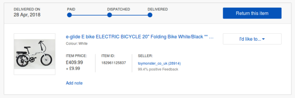
It's an "eglide folding ebike" and it sells on eBay for around £400 and comes with a ~200 Watt-hour battery, which is small but adequate. The battery is easily the most expensive part of the bike.
PAS LED displays
My ebike came with a "3-mode PAS" (pedal assist system) with an LED control panel that looks like this:
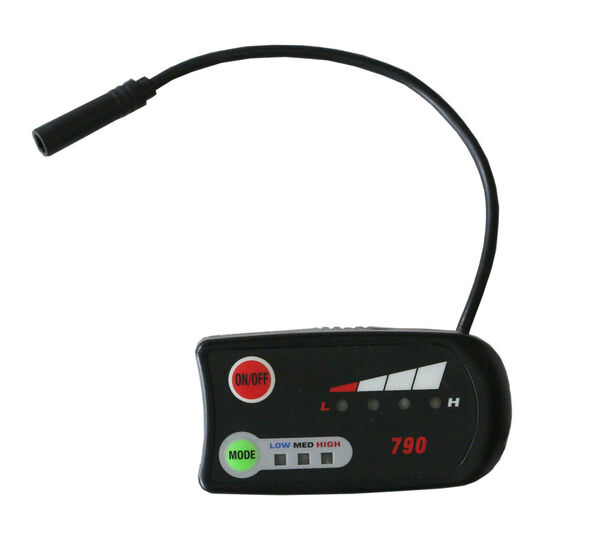
(To disassemble it, you need to peel the label sticker off the front and then undo the screws that are hidden underneath. Good luck getting it back together without horrible crinkles in the label).
You press the power button at top left to turn the system on. It then indicates the battery level using the upper 4 LEDs. The lower 3 LEDs are used to indicate the 3 different levels of assistance, which you can cycle through using the "mode" button.
There are a handful of other variations on this type of LED display:
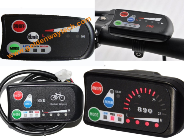
But I suspect they all work in largely the same way.
I have some ideas for UX improvements, so I intend to implement my own control panel, but in order to do this I needed to understand the wiring. I couldn't find any documentation online so I worked it out on my own, and I'm sharing it in case it's useful to anybody else.
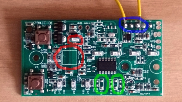
(I soldered the two yellow wires on to facilitate powering it up on the bench).
Circled in green are what appear to be two more spots for pedal assist level LEDs to be placed. I assume the same PCB can be used for 5-mode PAS systems as well.
The large red circle shows a location for another microswitch, which is used to switch the lights on and off on other variations of this control panel, and the smaller red circle shows the LED that I believe indicates whether or not the lights are switched on, which seems to have been placed on my PCB by mistake - it never comes on and there's no hole in the front label to show it even if it did.
The blue circle shows the location of the wires that were connected to the panel.
Wiring
My control panel had 4 wires connected to it, with the silkscreen labelling them as "VCC", "K", "GND", "TUO". These are as follows:
- GND is ground. Battery negative.
- VCC is connected to battery positive (it's not voltage-regulated before reaching the control panel, so the voltage drops as the battery runs down).
- K is used to switch the system on. When K is pulled to VCC, the pedal assist system is enabled, otherwise the motor doesn't come on (some ebikes have a hand throttle in addition to the pedal assist system; I don't actually know if disconnecting K from VCC disables the motor entirely, or only disables the pedal assist system).
- TUO is used to set the pedal assist level, in a range of about 2 to 4 volts. I don't yet know whether this is an analogue signal that can vary continuously, or if the motor controller only supports 3 distinct modes (update: it's 3 discrete levels).
There are a handful of other wire pads on the PCB, labelled "TX", "DD+", "ZB", "SC". I don't know what these are for. Presumably at least one of them is for switching the lights on and off. Please email me if you know anything I don't know.
Pedal assist voltages
| Assist level | Voltage on TUO |
|---|---|
| LOW | 2v |
| MED | 3v |
| HIGH | 4v |
Update: I found that if "K" is pulled high, the bike is on at least the "LOW" assist level even with no voltage on "TUO". I also didn't observe any ill effects from connecting "TUO" directly to "VCC". This means in a pinch you can get a working system by just twisting the VCC and K wires together, and then twisting TUO on to it to switch from LOW to HIGH assist level. I actually rode with VCC, K, and TUO twisted together (with GND safely taped out of the way), and no control panel at all, for about 20 miles and it all worked fine. Probably not advisable long-term.
Battery levels
Voltages are approximate, but should be correct to within about half a volt. Note my bike has a 24v battery. Other batteries will obviously have different voltage ranges.
| Battery voltage range | LED pattern |
|---|---|
| > 25.6 | 4 solid LEDs |
| 24.2 - 25.6 | 3 solid LEDs |
| 23.6 - 24.2 | 2 solid LEDs |
| 22.0 - 23.6 | 1 solid LED |
| < 22.0 | 1 flashing LED |
I don't know at what voltage the battery management system cuts the power, but I guess it's not too far below 22 volts.
UX improvements
The (minor-ish) issues I have with the control panel are:
1.) It always starts out in "LOW" assist mode regardless of what it was on last time.
When I first switch the bike on I normally want the acceleration to get me up to speed quickly, so I always have to manually switch it to "HIGH" assist as I set off.
2.) When you press the power button it spends a good 3-4 seconds going through some LED flashing sequence before actually getting into a state where you can use it.
If I've been cycling along with the system switched off and suddenly want some quick assistance (for a small hill, or because I had to stop unexpectedly and need to accelerate again), I need to press the power button, wait 3-4 seconds, and then press the "mode" button twice to switch it to "HIGH" assist mode.
3.) The pedal assist levels are not sufficiently fine-grained.
When trying to ride with another person, it's nice to ride at exactly the same speed. I've found that the "HIGH" assist mode makes the bike go too fast even with no power input from me, and the "MED" assist mode is too slow unless I pedal harder than I'd like to. I want more levels in between.
4.) The battery indicator level is not sufficiently fine-grained.
In good conditions I can go a good 45 minutes on "HIGH" assist and still have 4 solid LEDs of battery level. Then over the course of the next 20 minutes it drops from 4 to 2 LEDs. It would be better to have a more precise idea of the amount of battery power remaining.
5.) It's impossible to choose the assist level without looking down at the display.
The only way to change the assist level is with the "mode" button, but the mode you move to always depends on the mode you're already in, which means you need to look at the display to know which mode you'll move in to. Additionally, while the system is booting up, it does not register presses of the "mode" button, so you need to look at the display to wait for the thing to be ready before pressing the button will change the mode.
So I'm planning to design a new system using an Arduino Nano, a 160x128 LCD panel, a potentiometer with a thumb-controlled lever for the controller inputs, and a 3d-printed case. I'd like to have a tactile click at the start of the potentiometer travel, at which point the "K" wire is switched on, the display comes on, and the system is enabled. Then I'd like the rest of the potentiometer travel to linearly increase the pedal assist power, rather than stepping between 3 discrete modes.
In the event that the motor controller only supports 3 different modes, I'll try to pulse-width modulate between a low mode and a high mode to get the equivalent of a smooth scale. I'd like the system to "boot up" quickly and be operational almost immediately. I'd like to display the battery power in a vertical bar on the LCD, like on a mobile phone. I'd also like to show the speed on the display, by using a hall effect sensor and a magnet like on the scooter speedo driver. Finally, I'd like the case to be relatively small and elegant, and not obviously a DIY bodge-job, but we'll have to wait and see whether my CAD skills are up to the task.
This should solve all of the problems I identified with the existing control panel.