
My racing mower has a tendency to over-rev on long straights. To avoid damaging the engine, we have been lifting off the throttle, but a more reliable solution would be an electronic rev limiter. I did buy a commercial rev limiter made by AccuSpark, but was unable to fit it to my mower because the AccuSpark unit needs access to both sides of the ignition coil, and my ignition coil is inaccessible, inside a black box with all the other ignition electronics. So my solution was to make a rev limiter with an Arduino.
To limit how fast the engine can run, our project just needs to measure how fast the engine is running, and kill the ignition when it's running too fast.
Sensing RPM
The flywheel has a large magnet on it for the ignition electronics, so to detect the engine RPM I bent up a small piece of steel to hold a magnet sensor near the flywheel:
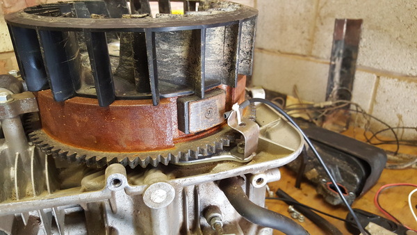
This triggers an interrupt in the Arduino code once every time the engine rotates, and the time between interrupts can be used to calculate the engine RPM (e.g. at 20ms between interrupts, the engine is turning at 3000rpm).
Killing the ignition
The black box ignition electrics provides a convenient way to kill the engine, you just short the kill switch wire to ground and then the signal for the spark is shorted to ground instead of generating a spark. The downside is that this is quite hard to do electronically. From what I've read online, the signal on this wire is roughly a 15 microsecond pulse of 150v AC.
I first tried to switch the kill switch wire with an NPN transistor, but couldn't get this to work. I also tried an N-channel MOSFET and couldn't get that to work either. In both cases, everything I tried either never killed the ignition, or always killed it.
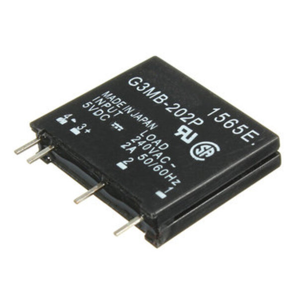
Eventually I bought a solid-state relay and that worked much better. I suspect the problem was that the transistor and MOSFET can't handle the voltage, AC, or both, whereas the solid-state relay is designed for 240v AC. You might get away with using a mechanical relay instead of a solid-state one, but driving it is inconvenient as it takes more current than the Arduino outputs can supply, and the rapid switching would result in premature wear.
The solid-state relay I used was an Omron G3MB-202P, and it looks like this:
Installation
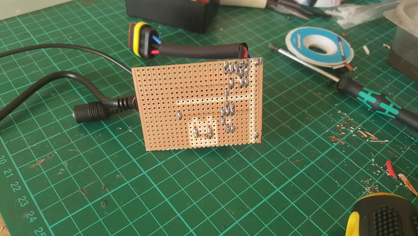
Having made the rev limiter work on a breadboard, I made up a piece of copper stripboard with an Arduino Nano, the solid-state relay, and the requisite connectors:
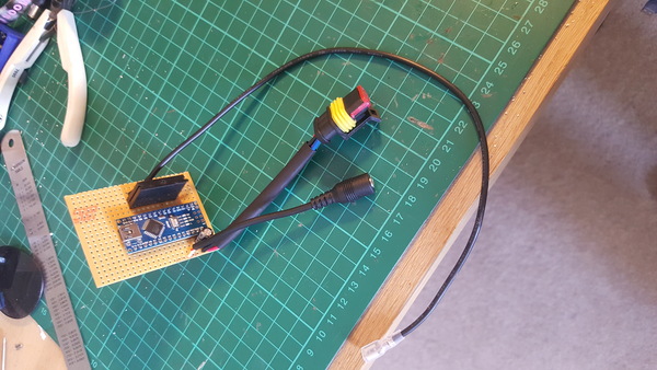
(although, the project is simple enough that you could get away with ignoring the stripboard altogether and just soldering wires between the components).
I carved out some isolation around the high-voltage parts because I was paranoid about the 150v pulse arcing to adjacent traces and damaging the Arduino, but the gap is probably large enough that it wouldn't.
The connectors we need are a USB cable for reprogramming the Arduino, a connector for power supply from the mower battery, a cable to connect to the hall effect sensor (with 2.5mm audio jack for convenience), and a wire to connect to the kill switch wire (with spade connector).
I 3d printed a case:
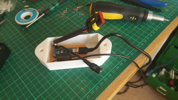
As you can see, the actual project only takes up about half the space inside the case. The rest is taken up by the inconvenient USB plug. A much better way to design the case would be to have the wires coming out of one end instead of out of the top. It would also be helpful to lie the solid-state relay on its side, parallel to the Arduino.
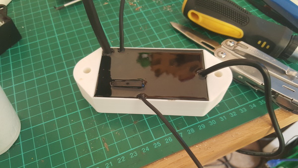
I potted the board in to the case with polyurethane resin to protect it from water and vibration:
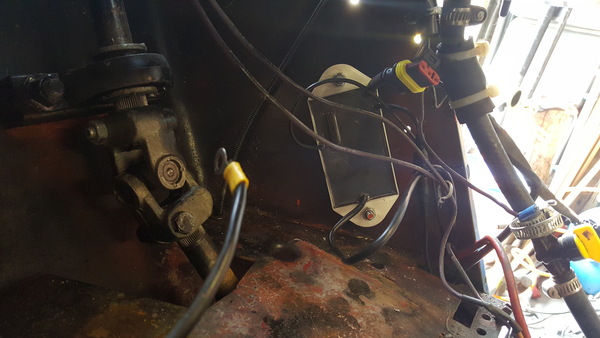
and bolted it inside some bodywork on the mower:
The last Arduino project I did for a vehicle was the speedo driver for my scooter. Lessons learned from that project include:
- an Arduino Nano is easier to use than a raw ATmega328p, as it includes its own voltage regulator and a USB connector
- female connectors on the circuit board are to be avoided as they are liable to fill up with resin
- it's easier to secure the electronics to the vehicle if the case has mounting holes
Software
You can get the Arduino code on github. It's not very complicated. It keeps track of the last 2 times (in microseconds) at which the interrupt fired, and then the main loop is a busy loop that constantly checks the current RPM based on these times, and makes the relay connect the kill switch wire to ground if the RPM is too high, and disconnect it if the RPM is low enough.
I also made it put the microcontroller into sleep mode after the engine has not been running for 10 seconds, in order to avoid wasting power spinning the busy loop while the engine is not running.
We have ran the mower for 2 or 3 hours with this rev limiter, and it still seems to work.
I have a video demonstrating the rev limiter, although in the video the engine is not bolted down properly, and the Arduino code only measures the RPM with milliseconds instead of microseconds. But it works, and it shows the idea.
The program writes the current RPM to the Serial console 10 times per second, suitable for use with the Arduino "serial plotter" to get a live plot of the engine speed.
The redline is configured by editing the max_rpm constant in the Arduino code. I expect this will be fine, but if you expect to have to adjust it a lot, you could read it off a potentiometer instead.
The worst part about editing the code in-the-field is that the laptop screen can be hard to see even on an overcast day:

Better mounting holes
In addition to reorienting things so as to use the space inside the case more efficiently, I thought it would be a good idea to make the space around the holes hollow:
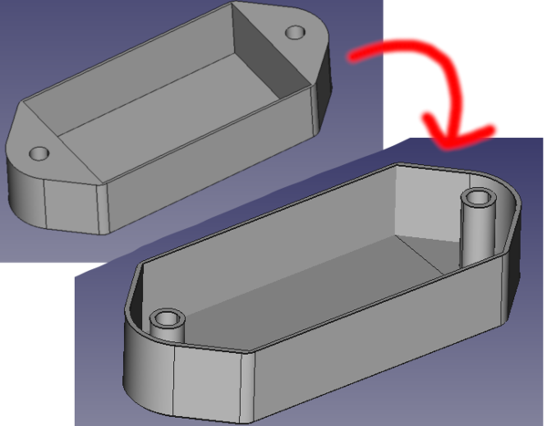
This would actually be stronger, as the resin would reinforce the holes, instead of just relying on the strength of the 3d print.