Last modified: 2025-06-17 21:37:37
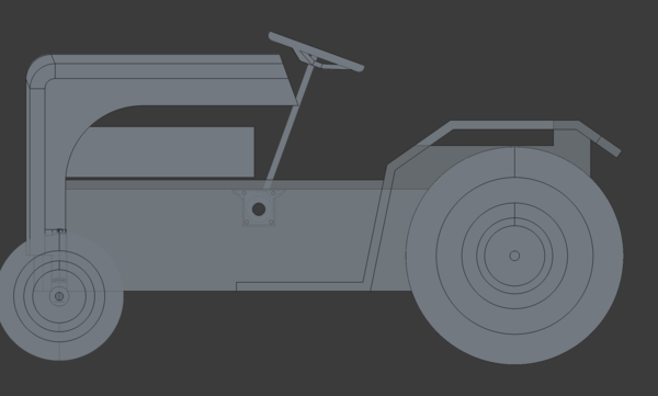
< 2025-06-16 2025-06-18 >I've designed a steering gearbox in FreeCAD:
It holds the angle grinder gears.
Quite a complicated part though. The plan is to 3d print it in PC-Max, and if that turns out not to be enough, then... struggle.
It needs to be able to come apart into two halves so that the shafts can be installed.
And, happily, after the rod end is on the front steering arm, the pivot of the gearbox will be 27mm above the plane of the steering rod. I wanted about 25mm arm length, so that is basically spot on. That's better than the precision of the woodworking that the chassis is made from, and will be dwarfed by the range of motion of the swing axle. Excellent.
So for the 2 horizontal shafts coming out of the gearbox, the inner bearing is inside the gearbox, and you assemble the gearbox with the shafts already installed... so how do I get the shafts through the holes in the chassis? Bugger.
If I make the chassis holes over-sized so that I can stick the shaft through it at a diagonal then it might be possible?
They can't be too over-sized because they need to hold bearings. Plausibly the bearings could go on a separate part that is screwed to the inside of the chassis after the gearbox is installed.
Oh! I just need to install each half individually, and then bolt the gearbox together in-situ. Easy peasy.
Good, so I can 3d print this housing tomorrow. Probably go for a quick-ish test in PLA before printing in PC-Max.
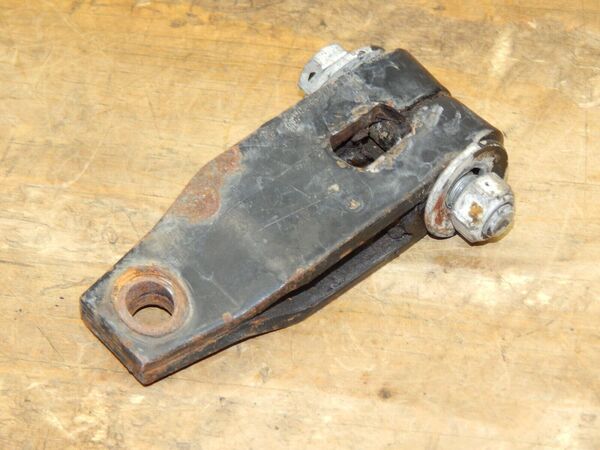
I also had an idea for making the arms out of 3mm steel, with the end bent over to make the bit you put the bolt through, like on this mower:

Although that is quite a bit thicker than 3mm, and the kingpin has flats on it to key it. Maybe I just have to accept that the steering arms need to be keyed. And then is 3mm enough or not?
There's also this, which is doubled up along its entire length: