Last modified: 2025-06-16 20:11:13
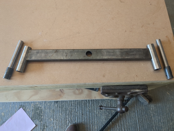
< 2025-06-15 2025-06-17 >A bit of work on the front axle beam:
And cut-outs on the chassis for it to swing inside:
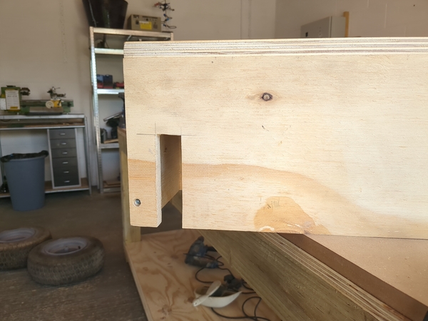
It is designed to swing by +/- 5°.
Obviously the axle beam needs welding, I'll plan to do that at the same time as welding the stub axles, so that I only need one session. And I think that should be the only welding I'm doing on this tractor.
I need to work out how the pivot is going to work. I do have a spacer that fits the hole I've drilled, and has a ~12mm bore, but it is a bit of a sloppy fit on an M12 bolt, so probably not suitable. Maybe I cut off a piece of 20mm rod and drill it to just-over 12mm, so that it is a tight fit on an M12 bolt?
The steering is going to work by having a bevel gear at the bottom of the rod that the steering wheel turns. This will engage with a pair of larger bevel gears, one on each side. So when you turn the wheel clockwise (steer to the right), the left-hand gear turns anti-clockwise when viewed from the left, and the right-hand gear turns anti-clockwise when viewed from the right. So then if you put an arm on the shaft of each of those bevel gears, pointing downwards, when you turn right, the left-hand arm moves backwards and the right-hand arm moves forwards. Connect those via rods to some arms at the stub axles, and it steers right.
I am thinking I'll 3d-print the gears at first, maybe that's a bit optimistic. I can always machine them out of aluminium later if they break. Actually, how easy/cheap is it to buy ready-made bevel gears?
If I want 3 turns of the steering wheel to move through 90 degrees of the real wheels, then I want about a 12:1 reduction, seems like a lot. Why does this always happen to me?
I'm also thinking I'll 3d-print the arms that go on the shafts, and machine them out of aluminium later if they break. I think print a keyway into the 3d-printed part, but don't yet put keyways on the kingpins. Get everything installed without keys, align it so that it works properly, and then mark where the keyways want to be and machine them then? I would kind of prefer not to have keys at the gearbox end, so that the arm angles can be adjusted. And if you're not having keys there, you don't need keys at the wheel either? Maybe try to live without keys to keep it adjustable?
ChatGPT reckons only 40 degrees of steering range is more sensible. So I'd want 3 turns to make 40 degrees, or 27x reduction?
I think the best source for bevel gears is angle grinder parts! You can get 2 sets of bevel gears for an angle grinder for £12 on Amazon, with ratio of 36:11, so that gives me the gears I need plus an extra pinion. Then it is just a case of fitting them to my shafts, which I'm sure I'll manage.
For the remaining 9x, I don't think I'll get there, but I can get maybe 2:1 in the ratio of arm lengths. If I put long arms at the wheels and short arms at the gearbox, then the angle that the wheel moves through will be less than the angle that the gearbox moves through.
To turn the wheel by 20 degrees with a 60 mm arm at the wheel, it has to move forwards by about 20mm. With a 2:1 ratio of arm lengths, the
arm at the gearbox would move around by asin(20/30) = 41°. So our full range of motion of 40° at the wheels is 81° at
the gearbox output, or 82 * 36/11 = 268° at the wheel. So still quite a bit more direct than I'd prefer, you don't even
get one complete turn of the wheel. Probably fine though.
If the arm at the gearbox were 25 mm instead of 30mm then it would move by 53° instead of 41°, for 346° range at the steering wheel.
OK, update on the swing axle pivot:
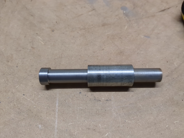
I used the aforementioned piece of steel as a spacer, the bore is more like 13 mm, maybe it's half inch? Or something random, don't know. And I turned up a pin to go through it, it is a nice running fit. And a hole in the front of the chassis that is a very tight fit. So then once the spacer is welded into the axle beam I can insert a plate of plywood in the chassis to take the back end of the pin, and then make some spacers to position the axle in the right place. And the pin will be held in place with a cross-drilled hole for a split pin, and a washer.
< 2025-06-15 2025-06-17 >