Last modified: 2024-08-24 20:24:22
< 2024-08-23 2024-08-25 >I finished modelling a prototype for this last night, started printing it now.
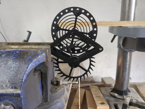
I put it together:
But it does not work.
The first error was that the spring keeps spinning around in the anchor attachment point, that one should have been square like the one on the balance wheel. I glued it in place to stop it spinning, but it still doesn't work.
It seems like the balance wheel swings for longer when it is moving freely than when it is being driven by the weight, so I think it does indeed subtract energy with each oscillation, instead of adding energy.
I think then that this might mean that the idea of twisting strings around each other also wouldn't work.
But then how does a normal anniversary clock escapement work? Don't they deliver the impulse to the suspension spring?
I should do a F=kx simulation, but have the spring centre point move every time the weight moves past the centre, and plot it. Does it gain energy or lose energy over time?
My plot suggests that the way I have this set up (centre point moves in the direction of travel of the mass) actually does add energy with each oscillation, which is good.
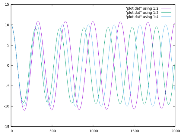
The purple line is matching what I have in my escapement (and gains energy over time). The light blue line doesn't move the attachment point at all, which keeps the energy constant. And the green line moves it in the opposite direction, which does subtract energy.
So then I think the issue with my escapement model is that it has too much friction. The anchor doesn't unlock until the balance wheel is well past the centre point, which means there is too much friction for the tension in the spring to overcome.
And maybe not enough weight in the balance wheel, which means it can only store weight in velocity, which uses up friction.
I made the standard blunder of not giving myself enough room between the frame plates to fit screws into the balance wheel.
So I'm saying obvious problems are:
Need to think about what to do about it. It seems like the idea should work, it is basically isomorphic to a normal anniversary clock.
Perhaps the spring is too light for the amount of energy we're trying to take out of the balance wheel, because there is so much friction on the "frictional rest" surfaces.
In fact, since this is not actually attached to a pendulum, we don't need any provision for a large amount of frictional rest. Maybe that's the problem here! I'm letting it "bank" over much too far. The anchor only needs to move far enough that there is a lock after the drop. All of the rest of the anchor movement should be putting energy into the balance spring.
Currently I've got the anchor lifting 2 degrees during the impulse, and then moving a further 5 degrees during locking. I should swap those numbers.
I've updated the CAD model to have 5 degrees of lift and 2 degrees of lock. Will print it overnight, but may struggle to fit it because the existing balance spring is glued into the existing anchor. If I can't break the glue joint then I will probably have to reprint both the anchor and the balance spring, and put a square end on it so it doesn't rotate.
I've put the table back on, with the vice bolted down directly to the table (which I've just realised is not necessarily sound until I surface off the top of the table, but never mind), and a piece of aluminium in the vice.
I'm going to do a test cut in the top and then measure it for accuracy, with a square, circle, and hexagon sticking up out of the top.
The recipe for the 6mm single-flute cutter was:
I'm doing adaptive clearing with 3mm step over and 2.75mm depth of cut and it is working very well! This is great.
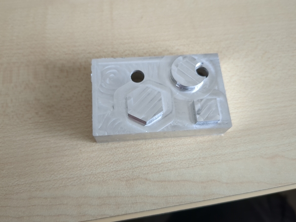
Running a fingernail over the lines doesn't catch on them, so I think the spindle is actually trammed satisfactorily.
The square is meant to be 10mm. With my 0.05mm vernier calipers:
So it looks like X is basically spot on, but Y has maybe some backlash?
Now with porch roof and dining room roof:
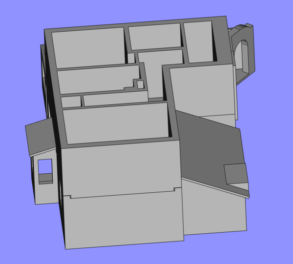
I really need to start measuring upstairs and finishing the first floor.
< 2024-08-23 2024-08-25 >