Last modified: 2024-07-26 14:24:20
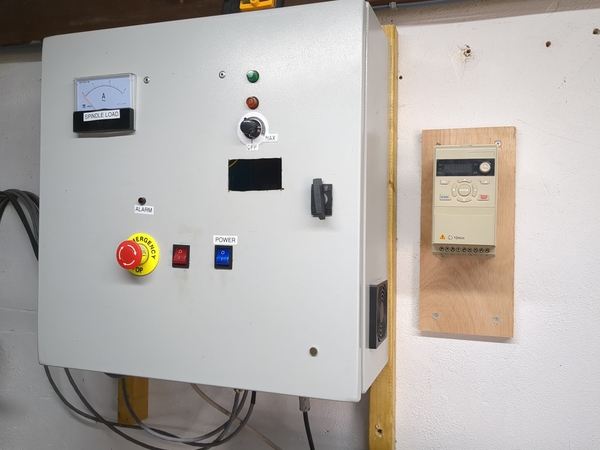
< 2024-07-21 2024-08-11 >VFD on the wall:
Now just needs wiring to the spindle motor on one end and the mains on the other.
It's an "EV50" VFD.
I've got it powered up with mains, and trying to configure it to set 400Hz as maximum frequency, and display that as 24000 rpm on the screen, not really succeeding though.
The documentation says that P00.13 is the "maximum setting value", which is 50 from the factory, and says:
limit setting value range. The unit of setting source is %, the maximum setting value (P00.13) stands for 100%, take maximum setting value as standard.
And there's also P00.14:
Motor operation frequency upper limit
So I was taking that to mean that P00.14 sets the maximum output frequency, and P00.13 sets the value that is displayed on the screen when you're at the maximum output frequency. So I would set P00.14 to 400 (Hz) and P00.13 to 24000 (rpm) and it would do what I want.
But that doesn't seem to be right, because it takes an incredibly long time to ramp up from 0 to 24000, so I think it might actually be ramping up to 24000 Hz, but once it reaches 400 it maybe doesn't increase the output frequency any more? So then I'd want both P00.13 and P00.14 set to 400 (Hz), but how do I make it display in rpm instead of Hz? Or don't I? I could just put a calibration chart on the wall next to the VFD.
It's showing "F000.0" at the moment, the "F" means it is showing frequency. Options are:
So I think maybe I want to try "H" or "t" mode to see if they look like they could be rpm. P10.98 and P10.99 don't appear to be documented. Are they internal values? And how do I switch display mode? Also why does the "REV" light come on as soon as I try to start it going? Why is it in reverse? Do I need to wire the reverse input to ground or something?
OK, you press the left arrow to switch the display mode. "H" mode seems to show a raw input from the potentiometer, ranging from 0 at the minimum position to -576 at the maximum position. I think it's raw potentiometer position rather than anything to do with output frequency because it responds almost immediately, whereas the frequency slowly ramps. "t" mode shows potentiometer position as a percentage, ranges from 0.00 to 100.1.
So unless I can make it display some ratio of the actual frequency, it looks like it doesn't have a way to show rpm.
I'll set P00.13 to 400 and P00.14 to 400 and leave the rest of the settings as factory default. And now the reverse thing has fixed itself.
It looks like the acceleration time is too slow, but I'll deal with that once I connect up the motor.
For now I'm at defaults, but:
Next up is wiring it up to the motor.
Using the multimeter in resistance mode I have determined that the pin furthest from me is the earth pin on the motor, because it has no continuity to the other pins, which all have some continuity to each other via the motor windings. And in fact that is labelled on the connector as pin 4, with an earth symbol adjacent, so that's good. I'm using the green conductor for earth. Pin assignments:
In the event that it runs backwards I'll obviously have to swap two of U/V/W.
I wired it all up and tried to start the spindle. At 0 Hz it is a bit vibrate-y, and when I started speeding it up the VFD displayed "E0006", fault 6 is "output short circuit" - "inverter cut off output when inverter output current is 250% larger than inverter rated current".
I can't measure any short with the multimeter.
Maybe if I try turning the potentiometer slower?
Now "E0007" - "output over current".
I'm getting 2.5 ohms between U/V, U/W, and V/W, measured at the terminals on the VFD. Should be fine.
Maybe the output voltage is set too high.
P00.73 sets "motor voltage", is set to 220v. I'll change that to 20v and see what happens. Seems to work!
Maybe the output needs to be only 120v? I'll just play with it at 20v for now.
There is a weird thing where it starts moving at a low frequency, and then stops moving as the frequency increases, and then starts moving again.
I've changed P00.74 "motor frequency" from 50 Hz to 400 Hz, and now it doesn't move at all. If I set voltage back up to 220v?
Whoa, works much better now!
You can hear the motor speed "hunting" quite a lot, maybe some PID loop needs tuning. I'm going to put a tachometer on the spindle to see if it is going at the right speed.
Getting 1350 rpm at an indicated 24.6 Hz.
1350*400/24.6 = 21951, so this is broadly correct!
Getting 3580 at 60 Hz, 3580*400/60 = 23866, so, very good. This is working as intended. And it accelerates at a decent rate as well. I ran it all the way up to full speed and held it there for a second and brought it back down and nothing went wrong. Obviously it should be able to stay at full speed for ages, but I don't have the coolant connected at the moment so don't want to overheat the motor.
Next steps: