Last modified: 2024-05-22 20:06:56
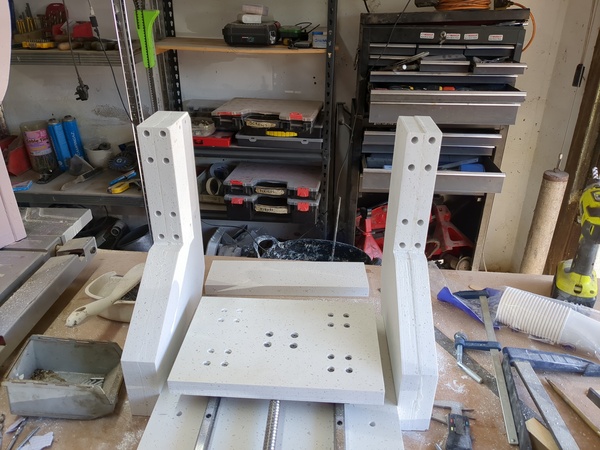
< 2024-05-19 2024-05-30 >I think I was wrong yesterday when I said the gantry needs shimming up at the left or right. If the gantry is tilted left/right then our whole coordinate system tilts left/right and we don't care. The top of the table will get surfaced down and everything will be fine, no?
I did shim up the left hand side with a bit of paper, but I'm not going to worry about getting it very exact, I'll just mark the holes where they are now. I can still shim one side forward/backward without losing the alignment with the bolt holes.
So plan is:
With the gantry clamped on I put a tiny drill mark in the top and bottom holes to mark the locations.
Template printed, holes drilled:
Next I need to roughen up the inserts on the lathe, then epoxy them in. And must remember to plug up the unwanted holes in the baseplate.
In 2024-04-29 I said I mixed the epoxy filler with 50% powder by weight, but today I tried that and it was not runny at all:
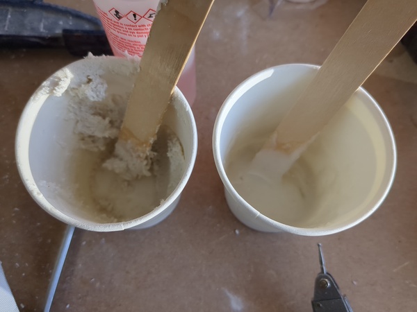
The top one is 50% by weight, the bottom one is 1/3rd. So I think I actually did 1/3rd the other day as well: equal parts resin, hardener, and powder.
Even with the runnier filler it was hard to fill up the holes because I kept trapping air bubbles, this is what I'm left with now:
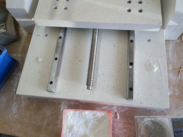
In a couple of hours I need to come and scrape off the bit I dripped on the linear rail, unbolt the template from one upright, and glue inserts into the other.
51 minutes for the drilling template to print, I'll try and CAD some motor mounts now. I think it would be most convenient if all the motor mounts were the same. Not sure how feasible that is going to be.
The X and Y motors overhang their plates slightly, but the Z motor overhangs a lot:
Well here's a first iteration:
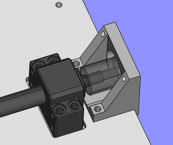
I don't really like it:
We know that the bracket only needs to resist torque. The triangulation is basically pointless, and the bolting point wants to be closer to the motor.
The lower motor holes are blocked off by the baseplate, but I probably don't care. Just 2 bolts should be enough. If it turns out not to be then I probably transfer the holes from the bracket into the baseplate and put threaded inserts in the baseplate.
This looks better:
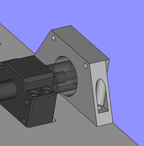
It fits the X axis as well if the square face is extended by 5.5mm. That seems close enough that I might be able to get away with using the same bracket dimensions for both, if I move one of the motors.
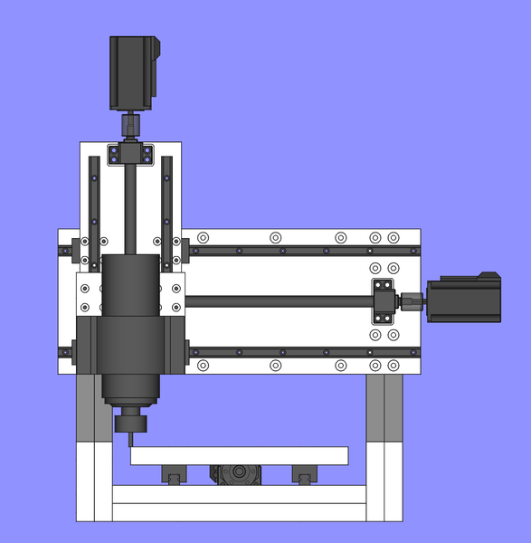
I'm trying to work out why I designed the Z axis the way I did. Wouldn't it have worked just as well if all the leadscrew stuff was moved further down? Would have saved me the hassle of trying to make a complicated motor bracket.
< 2024-05-19 2024-05-30 >