Last modified: 2023-11-28 22:17:25
< 2023-11-27 2023-11-29 >The Harrison clocks all have remontoires that rewind periodically, with the rewinding getting more frequent as the clocks get more advanced.
Instead of a periodic rewinding, why not have the remontoire be completely continuous? I.e. it is a component that passes torque only up to a given limit.
You could imagine providing torque via a torsion bar, so that as more torque is applied, the bar twists more. Then you have a sliding piece keyed to one end of the bar, with "axial cams" on a disc at the other end of the bar, so that as the bar twists, it pushes the sliding piece axially, and you'd have the sliding piece operate a brake on the input, so that the input is braked proportionally to its torque.
Does that get you a constant torque output, or does the output still increase as the input increases? It feels like the latter to me, but maybe it is adjacent to an actual solution.
OK, what about this idea:
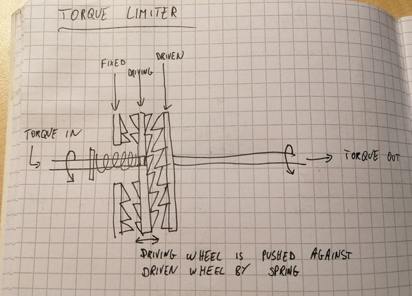
We start with a ramped wheel like the torque limiter in a cordless drill. Both the driving and driven side have ramps on. The ramps on the driving side are pressed against the ramps on the driven side by a spring. When the torque is too high, instead of transmitting torque, the spring compresses, the driving ramps move away from the driven ramps, and it skips a tooth.
That is a perfectly good torque limiter, but it responds to excess torque by letting it spin "freely", which is no good because it will wind down the mainspring very quickly.
So we start with that mechanism, except we have a third ramped wheel fixed to the frame, unable to rotate, positioned so that the driving wheel catches against it if it tries to ride up the ramp of the driven wheel. So the driving wheel will then be stuck against the ramps on the frame until the driven wheel has moved around a bit, and then the driving wheel will slide down the ramp on the frame and become able to apply torque to the driven wheel once again.
Like this:
OK, having drawn the diagram, I can see that the fixed wheel shouldn't have ramps on it, because then more application of torque will push the driving wheel back into the driven wheel and allow it to turn with more torque than it should.
But if the fixed wheel has non-ramped teeth, it seems like friction against the fixed wheel might make it bind up and stop entirely, even when there is no back-torque from the driven wheel.
Needs more thought.
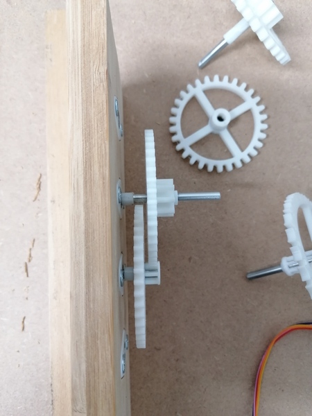
I cut away part of the spacer that was interfering with the second wheel and it all works really well now:
https://www.youtube.com/watch?v=fka4tlPO7vA
So I'm going to start printing parts for the other clock, except I'll have 2 copies of the shortest spacer and none of the mid-sized one.
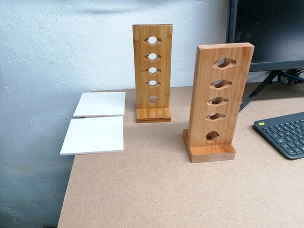
Both frames assembled, and with one coat of lacquer, and 2 coats of white paint on the blanks for the dials:
I've also got the second clock's gears all installed on shafts, just the electrical cover printing and then that's all the printing done for that one.
So, tomorrow:
I wanted to cut the flat on the third wheel shaft for the second clock, but when I went to use the milling machine the Z axis motor was broken again! It just moves a tiny amount and then trips the alarm, as if the servo feedback isn't working.
I tried hitting it with a hammer again but it didn't help.
I solved my immediate problem by unplugging the cables for the Z axis motor and turning it manually, to position the head for cutting the flat on the shaft, which has worked, but I'd really like this machine to work properly.
Well I took the motor off again, took it partially apart, and it started working. I don't know what changed.
To save me the trouble of having to undo the bolts from the bottom, I have tapped M6 threads in the motor housing, and drilled out the holes at the top of the Z axis, so now it bolts on from above, much more convenient.
I have a theory about what was wrong: I think it might be caused by the backlash compensation. I had 0.35mm configured for the Z axis, and maybe when the motor is cold the backlash compensation makes it try to accelerate too fast? Or, maybe the issue is just that Z acceleration is set too high? Not sure. It's working again for now anyway.
I've reimplemented my regex.pikevm in SLANG as a first pass, and it seems to work in trivial
regexes.
https://github.com/jes/scamp-cpu/commit/135ce6806986d3d700da9b7aaba4d0bbeed61840
I am having trouble testing it on harder regexes because my shell's input escaping is not working properly.
$ re 'a*b' aaab
sh: parse error
$ echo 'a*b'
sh: parse error
$ echo 'foo'
sh: parse error
So I need to fix this next.
< 2023-11-27 2023-11-29 >