Last modified: 2023-11-16 22:09:20
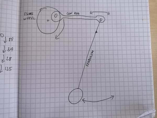
< 2023-11-15 2023-11-17 >Last night I was dreaming about escapements and had a few interesting ideas for designs that reduce sliding friction at the pallets:
I think all of these would be totally silent as there are no pallet impacts.
I think the crank and cam versions would be very poor timekeepers because they don't allow the pendulum to swing freely. Take the crank for example:
You can see that the amplitude of the pendulum is constant! The escape wheel either has enough torque to drive it to this amplitude (in which case it runs faster than it naturally would, getting worse as torque increases), or it does not (in which case it stalls).
One downside of the crank escapement is that it needs a higher-ratio gear train than a normal escapement, or the cam escapement, because you only get one cycle of the pendulum for each revolution of the escape wheel.
I think the eddy current version be an even worse timekeeper because I think the eddy current brake will not make it run at a constant speed, and also presumably the braking will change based on temperature as the resistance in the escape wheel changes.
The "magnetic escapement" idea is definitely interesting but I can't quite see how it would work. You can imagine some permanent magnets on the escape wheel (of alternating polarity?) and some on the top of the pendulum, and as the pendulum swings back and forth it alternately lets a north and a south pole pass above it? Not quite sure how it would work. Probably it would also be a poor timekeeper without something to actually stop the escape wheel, else it still has the problem that the escape wheel is constantly applying force to the pendulum.
I think I would be interested to analyse the crank escapement to work out how badly it would perform in practice. Maybe a Matter.js simulation is the easiest way to play with it?
Devine Lu Linvega put a post on the CollapseOS mailing list about a data compression format for small systems: http://wiki.xxiivv.com/site/ulz_format.html - although it doesn't appear to have an encoding algorithm yet.
But maybe SCAMP would context switch faster if binaries were stored on disk in a compressed form!
Compressing lib.o with gzip takes it from 9K words to 3.5K words, so could potentially
be useful. Although I've just remembered that disk IO is basically CPU-bound anyway, so making
the CPU do more work is probably counter-productive.
Anyway, first job is to work out why the behaviour of the impulse pin in the slot does not match the CAD.
One hypothesis is that it is caused by flex in the frame. The only thing constraining the left half of the model to the right half is the flimsy back-plate.
An interesting design might be to have the balance cock "underneath" the top plate. So you'd have a bottom plate spanning the whole model, then the balance cock mounted on one side, and then a top plate above it also spanning the whole model.
Something like this:
Another hypothesis is that something about the assembly of the pallet fork is crooked, but The pallet pins are slightly crooked, but it doesn't look too bad to me, and they're both pointing in the same direction.
Well anyway, whether it is the frame or the pallet fork that is crooked, it pretty much works anyway, and I could modify the slot to have tolerance for it, so I will do that.
So, print the new pallet fork, and then run some isochronism tests with different weights, and assuming it's isochronism is reasonable, I think I'm done with this model, and it becomes the new preferred design for the watch. And maybe I try printing a 1x scale model with the 0.25mm nozzle? It would be good to have a way to scale a model in FreeCAD, to save doing it all by hand.
It's running pretty well now. This time with just the allen keys and no room spray for a weight (which comes to 370g) the impulse pin is sometimes hitting the balance cock! The amplitude does vary throughout the escape wheel rotation, I think there is still some eccentricity, but not as bad as with the previous escape wheel.
So to run a watch like this would require only 10.7 Nm instead of 16.4 from yesterday. Still too much, obviously, but made smaller and with less friction it would be less.
The impulse pin is still rubbing slightly against the top of the slot, but I'm still not totally sure why. I think the pallet pins are pretty straight now, so that's not the problem. I tried twisting the frame by hand but I can't fix it. I tried re-mounting both cocks and that hasn't fixed it.
The crazy part is that in CAD it shows it getting closer to the lower edge of the slot. (And, actually, still rubbing slightly). Oh, well, whatever. Let's do some isochronism tests with different weights.
I was surprised to find it runs with just 1 nut, which is 87 grams, albeit with quite low amplitude. That corresponds to only 2.5 Nm to run the watch (but we'd want more amplitude). With 5 or more nuts the impulse pin hits the balance cock during the "good" part of the escape wheel.
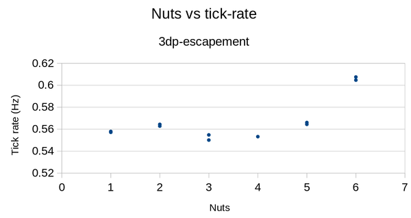
If you ignore the 5 and 6 nut cases (where the impulse pin is hitting the balance cock), then from 1 nut to 4 nuts (factor of 4 torque increase), the tick rate varied within a range of about 0.550 Hz to 0.564 Hz (2.5%). I didn't plot a best fit line because of the obvious outliers at 5 and 6 nuts, and because only 4 different weights is not really a fair comparison to the previous tests. But the previous best was:
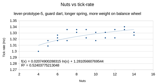
In which, over a range of 6 to 14 nuts (factor of ~2.3), tick rate varied within a range of about 1.318 Hz to 1.340 Hz (1.7%).
That escapement didn't even run over a factor of 4 in torque variation, so a really fair comparison can't be made, but over the range of 4 to 14 (all that I tested), the tick rate varied between about 1.30 and 1.34 Hz (3.1%).
Really I'm not interested in minimising the tick rate variation over such a large torque variation, what I really is to minimise the tick rate variation over the actual torque variation that I will have in the watch, variation of which I obviously will want to minimise.
Anyway, I think the experiment has proven that this new captive lever escapement performs broadly at least as well as the old one, with the obvious advantages that it runs over a wider range of torques, and can support larger amplitudes.
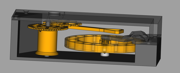
Here's some CAD:
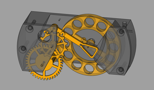
That's mostly the same design as before, but scaled down, and with a slightly different frame.
Shafts/pins required:
A 2h59m print with 0.25mm nozzle.
The stringing is quite bad, will take a lot of cleaning up with a knife, and probably under the loupe. Also bad elephant's foot, maybe I should be using a raft for these very small parts. The barrel gear is too flimsy for me to easily trim the elephant's foot with a knife.
Great, I printed the base piece without any screw holes. That's a 1h33m print on its own, more than 50% of what I spent so far. Also I forgot to put bosses around the barrel shaft holes. I'll print another barrel while I'm at it, just in case I get better luck with the elephant's foot this time.
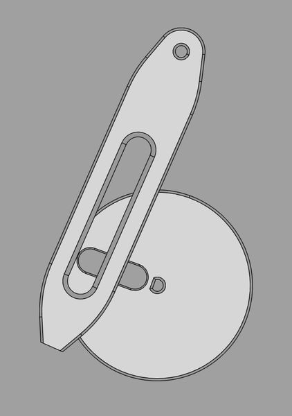
Here's another weird idea for an escapement: put a Scotch Yoke on the pendulum, and a pin on the "escape wheel":
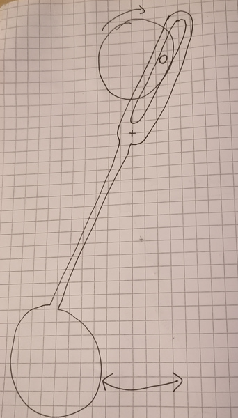
This will make the pendulum swing faster in one direction than the other, which seems obviously not ideal, and it still has the problem that the system will run faster if it has more drive torque, but might be interesting to try anyway.
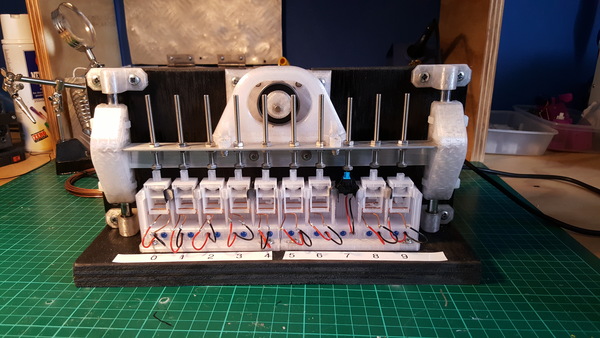
I'd obviously put a ball bearing on the pin like on the keyboard switch tester, to reduce sliding friction in the yoke:
You could make the radial position of the pin on the escape wheel adjustable, so that the amplitude can be adjusted. I'm not sure whether adjusting the amplitude or the pendulum length would be a better adjustment, or whether you'd want to adjust them separately for different things. For example, maybe you'd want to adjust the pendulum length so that its free-swinging period is correct, and then adjust the radial position of the Scotch Yoke pin so that the amplitude is high enough that the drive torque can just barely run it, to minimise the deviation from the pendulum's natural period? I don't know, I'm just guessing. I should build one and find out.
If you assume the pin is adjustable in the slot in the disc, then this arrangement can support amplitudes from about 15 degrees up to 47.5 degrees.
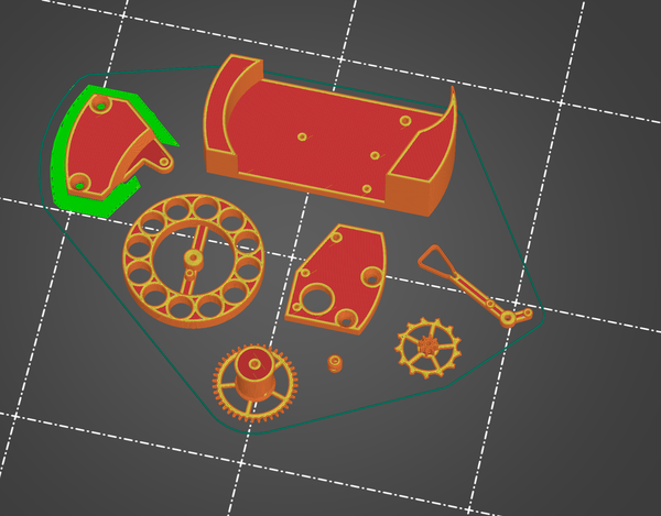
I've made a start on it anyway. Still need to design the frame, and there are a lot of parts "implied" that I need to make separately. I'm only modelling the ones I need to 3d print. Also needed are: