Last modified: 2023-10-22 09:32:18
< 2023-10-16 2023-10-18 >The first task was to open up the 0.5mm pivot holes in the die block so that the shafts can get pushed in all the way for wheels to be fitted.
Well rather than try to accurately align the CNC router on the holes, I decided to try to drill it by hand with a 0.8mm PCB drill in the pin vice. Obviously I broke the drill and it is now stuck in the hole. I knew this was going to happen and yet somehow that didn't stop me.
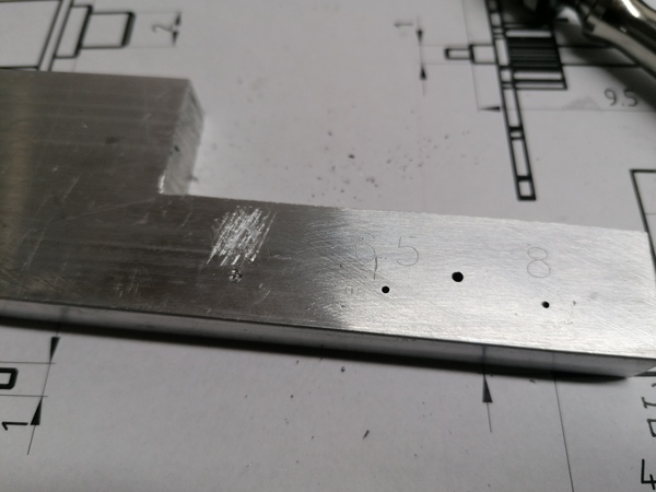
I've punched over the hole opening and scraped off the text so I don't try to use it:
But I will need to make this hole again. I actually did manage to succeed on the 6.5mm deep hole, and the 8mm deep one had a wider pivot hole to start with because it needed the length on the drill. So I need to buy a new set of PCB drills, and re-do the 4mm deep hole.
So, on to making new shafts. I need 3 but I think I'll make 4 so I can discard the worst one.
I have a pretty good workflow for doing lots of pivots at once on the 4th axis:
G0 X64 Y45 Z6G1 A360 F1200mk-pivotG0 X10 Y0 Z0G0 X64 Y45 Z6 againG0 A4000, G0 A0, while it's spinning, polish the pivot with the grey scouring cloth thingI found that the location of the high spot was aligned with the Sharpie mark on the 4th axis's backplate, and not with any of the other marks I left:
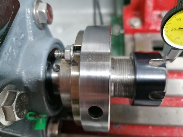
This means that the concentricity error comes from the register on the backplate. Do I need to re-cut it again?? How has this happened?
Anyway, great success, 4 shafts made and I think they're all better than the 3 existing ones, so this is progress.
I think I want to look under the microscope and try to take some measurements with Gimp.
First observation: the 0.06mm stepover is too big for the chamfers:
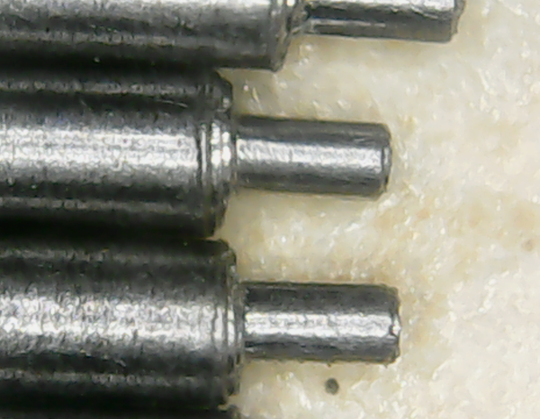
It leaves an obvious helix pattern on the chamfer. I need to make mk-pivot
use a smaller stepover value on the chamfers. It looks pretty good on the
actual pivots though, although maybe they could stand to be polished better.
I measured the shaft lengths (shoulder-to-shoulder) in Gimp at:
I measured them with Vernier calipers at:
Which implies px/mm of:
Which implies lengths according to Gimp measurement are:
So even the worst two are within 0.16 mm of the nominal size. Previously, the worst one was 0.4 mm long, so this is better than that, but actually still not as good as I hoped for.
The shafts have become wuite magnetised, not sure if this will be a problem.
I'll bank them for now and move on to shortening the standoffs.
Need to be careful not to make them too short.
Result: 9.65 mm and 9.60 mm. Decent enough.
I'm going to CAD a stepper motor clock based on 1:10 8:45 8:50, and then a conventional 1:3 1:4 to turn minutes into hours.
So we'll have:
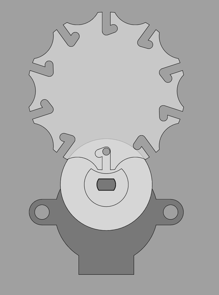
I came up with this for a one-way Geneva mechanism:
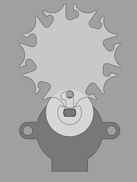
But the thin bit of material is less than 1mm thick, which isn't going to print very well, and the "catch" isn't particularly convincing, like I think it might just slip out and work backwards anyway.
Maybe need to rethink this. Maybe just make the pin smaller? Also the bit with the cutaway to allow the wheel to pass through is very thin, so maybe the diameter of that bit wants to be bigger.
Maybe this:
And here's a full gear-train:
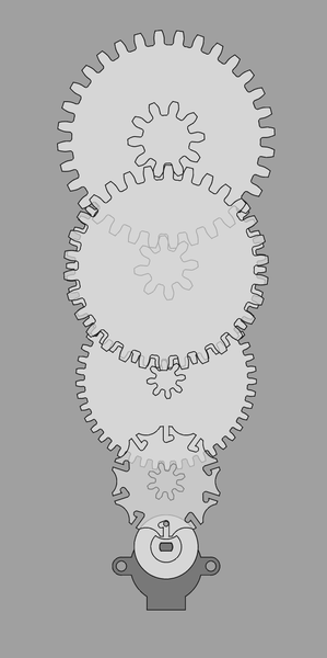
Including the bit that turns minutes into hours with 8:32 and 10:30. That part has larger teeth on the gears so that the shaft clears the minute hand's driven-gear.
It's 225mm tall. I could make it smaller by "curling it up", but I don't mind it being large.
Slightly better:
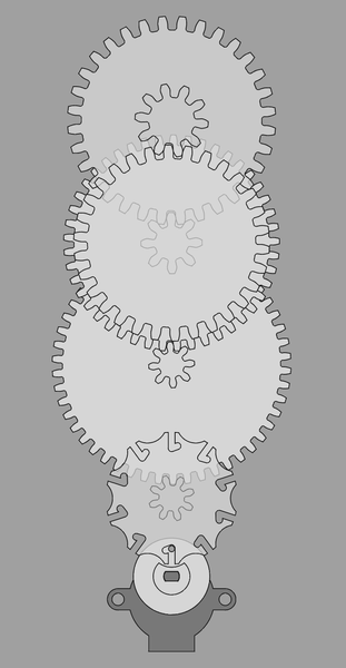
I swapped the second and third wheels so that the teeth of the counter-wheel thing could be smaller. Now 208mm tall.
I have plenty of bearings with 5mm ID, 10mm OD, and 4mm thickness, so I probably want to use those. Not convinced I have 5mm rod for shafts, but I can definitely do something about that (maybe turn down some 6mm rod, or in the worst case buy some 5mm).
I also have a handful of "6701" bearings, with 12mm ID, 18mm OD, 4mm thickness. Can potentially use these for the concentric shafts for the hands.
Well I made the holes for the shafts, but:
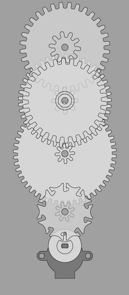
Oops, the second wheel interferes with the shaft for the third wheel. So maybe I need to swap the second and third wheels back.
Next steps on the stepper motor clock