Last modified: 2023-09-26 21:25:40
< 2023-09-25 2023-09-27 >Print out the guard dart system, make a longer spring, try it out, plot natural frequency of balance wheel & isochronicity charts again.
Tidy the garage, clean the lathe, make a chip-guard for the back of the lathe.
CAD a Douzieme gauge, make it, blog it.
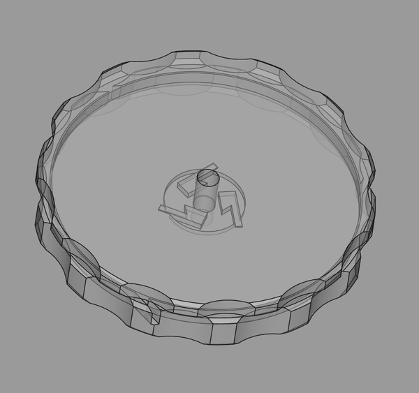
Well I printed the guard dart system out but I couldn't wind a satisfactory hairspring by hand, so I designed this hairspring winder based on one in the "Watch and Clock Making and Repairing" book:
Here's the one from the book:
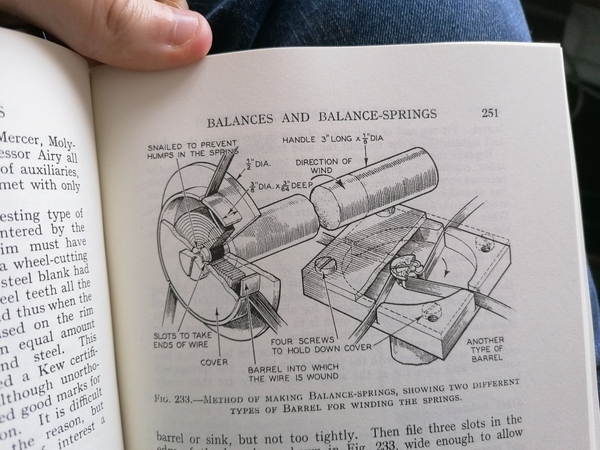
The idea is you hook 3 pieces of wire to the inside of one piece, and feed them through the slots in the other piece, and then rotate the pieces to coil the 3 wires up tightly together, and then you take it apart and you've got 3 hairsprings. Will it work? I don't know. The most likely failure is that the 3d printing is not precise enough to properly constrain the 0.7mm wire.
I had a lot of difficulty loading the wire, because it keeps falling out of its hook. I think if it were a hole you poke it in instead of a hook that lies in the same plane, it would be easier. I eventually taped down the 3 pieces of wire, with the idea that the winding motion would rip the tape off.
I also had a lot of difficulty bolting it up, because I had to hold an M3 nut and bolt at the same time as holding the lid shut with my fingers. I should put an M3 insert in the bottom part.
I also had a lot of difficulty doing the winding, because the tool is so small. I think it would be better if the handle on the top part were easier to grab, and if the bottom part had a rectangular piece to clamp in the vice.
When I opened it, it looked like this:
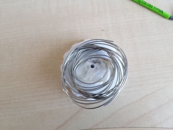
So the tape didn't rip up as easily as I hoped, and also the pieces didn't clamp together firmly enough so the wires were able to ride over each other.
Also it doesn't spring out very much once it's released, so I should make it bigger.
Let's try and design an improved version, using what we learnt...
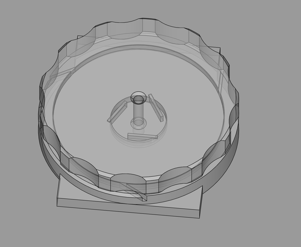
I know it looks similar but it is much larger. The grip on the top part is 10mm tall instead of 3mm.
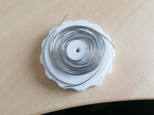
A bit more convincing, it still seemed like the wires were riding over each other though. Maybe try again with a clamping washer. Actually, this will do, I can work with this.
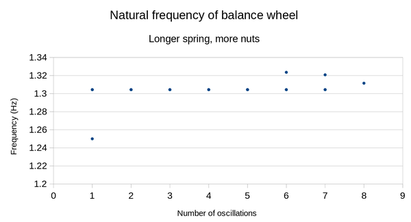
Boom.
Almost every data point is the exact same frequency. This is plotting 3 runs, but most of the time all 3 are on top of each other, which means the tick rate is consistent to within 1 frame of video, over like 5 seconds.
Very good, much better than before. I will measure the isochronicity of the escapement with the guard dart, but if the isochronicity is good enough now even at low amplitudes, then I think we can skip the guard dart idea and focus more effort on making a good balance wheel.
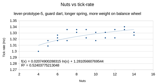
Mmm, actually not as good as last time (the coefficient on the log is 0.021 vs 0.017), although from 7 nuts upwards the actual data points look almost perfectly flat, at least within measurement error. If we follow the trend line, then from about 7 to 14 nuts is only a 1% change in tick rate.
One reason it might be worse is because the hairspring was clonking against the frame ever so slightly, which I guess means it acts slightly longer in one direction than the other?
With 14 nuts, we have 130 degrees amplitude:
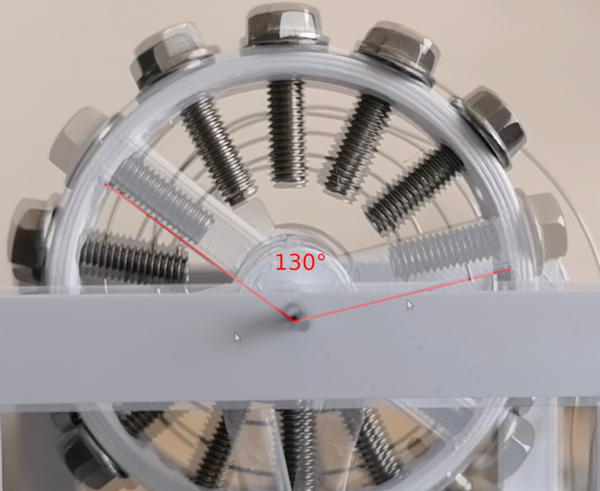
Seems like this would be possible even with the captive impulse pin?? Need to check.
Lol, just realised the guard dart I made doesn't even work because it allows the lever to start moving just before the pin enters it. That settles it then: no guard dart, it's too much trouble.
So I'm saying let's just go with lever-escapement-prototype3.FCStd for now and stop trying to improve it.
If it proves to be defective then I can revisit.
I designed this:
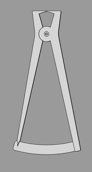
Based on the reference photo from the other day:
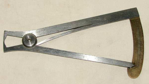
I'm planning to drill a hole on the inside of each leg and bend up a bit of stainless wire to make the spring. The pivot will be held together with an M3 bolt with a big washer, with one leg tapped, and maybe loctited. I still need to make the engraving pattern for the scale.
It's meant to be made out of 3mm steel, but if I find that too annoying I may revert to aluminium.
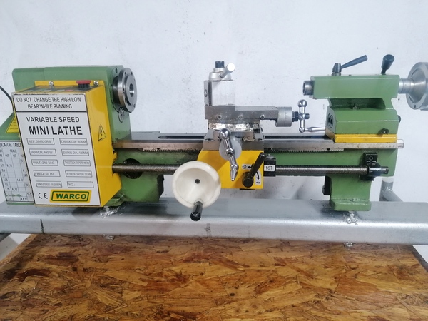
Garage is tidied, lathe is cleaned:
After lunch, make a chip-catcher.
Probably also want to fit the new blade to the bandsaw, and put it away somewhere, and maybe look at the tailstock of the lathe and see why it doesn't clamp properly any more.
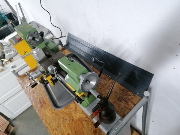
I cut up an offcut of roofing to make a chip-catcher:
While I'm thinking about the lathe: the carriage microscope is slightly too close to the work, the position where it's in focus is just beyond the end of its travel. Also it doesn't have enough travel left/right or forward/back, so I should make a new mount for it that rectifies these problems. Also the mount is a bit floppy, and it would be better if the eyepieces ended up at 45 degrees instead of vertical.
I designed this:
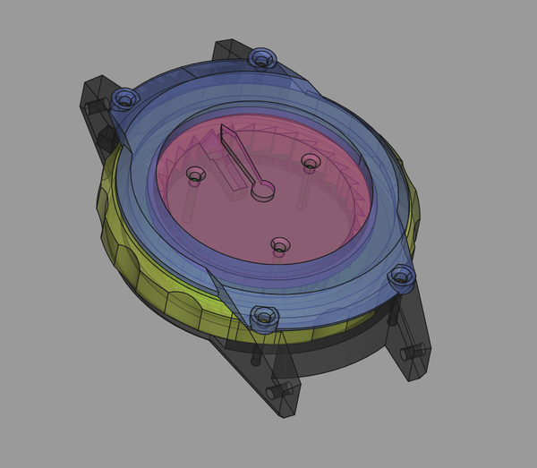
It has a dummy movement (i.e. no movement), but it is setup so that turning the yellow ring clockwise "winds it up" (spins freely), and turning it anticlockwise rotates the dummy movement inside the case. The hand is just fixed to the movement.
I don't like having the exposed screws on the top of the bezel, I would build the case the other way up next time (i.e. a plate screws on the bottom side, not the top side). And I don't really like the visual complexity,
Maybe some of the visual complexity is just from the colours and transparency, but it's still not exactly a pretty watch even with that turned off:
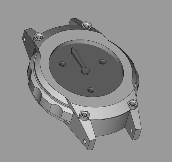
So at some point I will need to make it look nice, but for now this should be good enough to demonstrate the setting/winding principle, and find out whether it is easy enough to grab the winder.
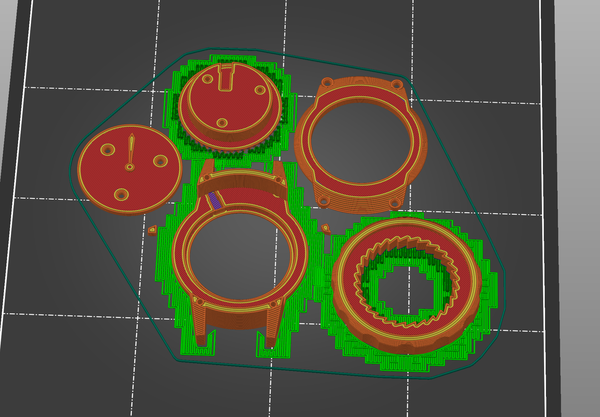
A 1h13 print, will be done about 10pm, at this rate I might be able to do several iterations before tomorrow! Hopefully this one works though. The most likely failure is the clicks for the ratchets, and thankfully they are the smallest parts.
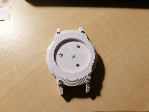
A reasonable success. The tiny 3d-printed ratchets don't work super reliably, but they do work a bit.