Last modified: 2023-09-26 07:39:08
< 2023-09-24 2023-09-26 >Simplicity is the ultimate sophistication.
-- Leonardo da Vinci (maybe)
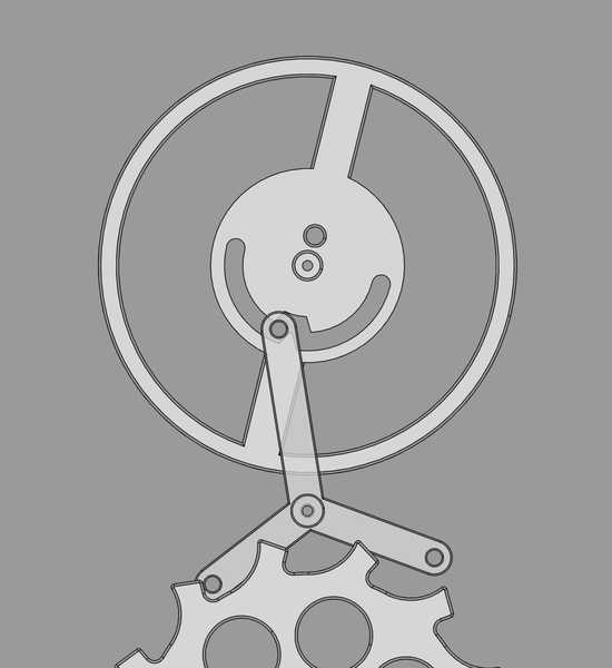
I think the idea of putting the slot in the wheel instead of the lever is not going to work.
I've been playing with configurations like this in FreeCAD:
It always seems like the pin can easily get stuck the "wrong" side of the notch in the slot.
I mean, it would work if the slot was just a vertical slot (like it is when it is in the lever), but then we don't gain any amplitude freedom.
I've left this in lever-escapement-prototype4.FCStd, but I'm not going to bother printing it.
So the next idea is probably to think of a simple way to make the "guard dart" system.
I've copied lever-escapement-prototype3.FCStd to lever-escapement-prototype5.FCStd and will
work on it in there.
Actually, before that, what if I just cut the top limit off the slot in the one I have? I want to see it working (and exhibiting banking behaviour) before I bother CAD'ing the guard system.
Yeah, it works, as expected:
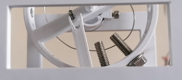
Although the bolts crash into the balance wheel pivot very soon after the pin exits the slot. Must remember to reduce the diameter of the balance wheel to accommodate the heads of the bolts!
What if I take the last bolts out? How much amplitude can I actually get?
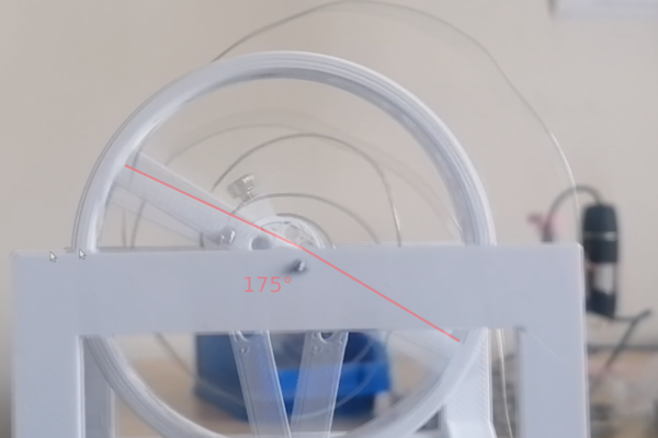
This is with me manually pulling on the string to provide more torque.
175 degrees, not bad! Pretty bad beat error though, I think there are not enough turns on the spring so we're into plastic deformation again.
So the plan is:
Here's the new CAD:
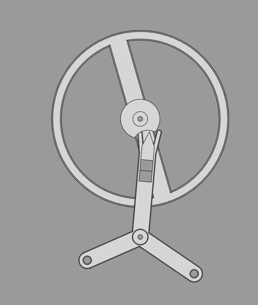
It's not very elegant, but at least I can try it out. Not sure how I'd machine this if it became miniscule.
I need to tidy up the garage, clean the lathe, and salvage a bit of steel from the roof offcuts to make a guard to stop chips and small parts falling down the back of the lathe.
I want to do a decent technical drawing of the escape wheel, at (provisional) final watch scale.
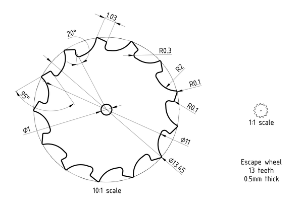
Is that fully-constrained? I don't know. It's more an art piece for the office wall than an actual technical drawing.
I loaded the new model in watch-mod02.FCStd to see what it looks like:
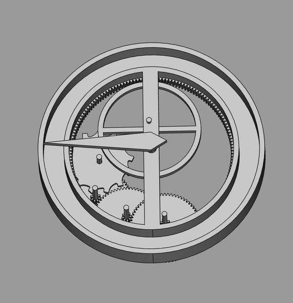
I noticed that all the gears in here are 1mm thick, which is unnecessary. Also the total stack is 18mm tall, which is too big. But we can address the thickness, because I know 0.5mm gears are easy to make.
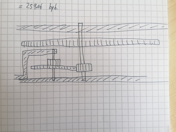
I started adding up the amount of teeth in the train, and I think the configuration here is going to run at almost 26000bph, which is way more than I want. It would be good if we could lose a factor of 2 or 3 and lose one of the gears.
It is certainly possible for gears to intersect the shafts of other gears (when viewed from above), if we have a separate "cock" or "bridge" that holds the shaft out of the way, like this:
So maybe the plan is to lose the last gear in the train (the one that currently drives the escape wheel), which would lose a factor of 8.5, and then make the one before that 3-4x as big, and make that one drive the escape wheel.
We also have the option to lose the "hollow barrel" design, but keep the "case-winding" idea, if we make the case-winding part have teeth on the inside which engage with teeth on the outside of the barrel to turn it, and then the barrel arbor drives the works. The benefits are we potentially get more space to play with, and we don't need to make the bearings work for a hollow barrel. The downside is it's now less than 1 turn of the case to wind the spring (so the "stop-work" indicator wouldn't work), it's more teeth to cut, and potentially more complexity.
I've copied watch-mod02.FCStd to watch-mod02-2.FCStd to try and experiment with losing a gear.
Making a 68-tooth gear 3x as big gives it 204 teeth, which is bigger than the inside of the barrel. This might not work. I may need to spread the increase around.
However currently the movement is only 44mm across. I'm happy to accept 50mm. For comparison the Bangle.js 1 is 50mm diameter and 18mm thick.
Obviously the "winding" grip will take up some space, so I'll just model in something for that and then expand the barrel to fit it.
And while I'm here I'll reduce the gears from 1mm to 0.5mm and maybe tighten up the gaps.
OK, so:
What about this layout:
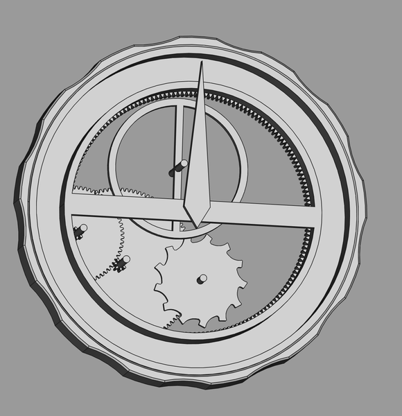
This leaves room for an "English lever" shaped lever, at the right-hand side of the pic.
I think the next thing to do on the movement layout is CAD the barrel more thoroughly, CAD the plates, and then look at designing the actual case of the watch, including provision for holding the dial & winding/setting.
I just realised that the shaft for the first wheel (the one with the pinion driven directly off the barrel) is extremely close to the barrel. It might be challenging to make the plate fit in there. There is less than 1mm clearance.
I also realised that needing to fit a bridge between the 2 wheels when they're already extending the height of the watch is maybe a big ask.
Maybe the better thing to do is just accept that there are 3 wheels, and adjust the numbers of teeth. That way we get to have larger pinions and we don't have to make extra bridges. Maybe instead of (68,68,68) teeth, we switch to (68,56,47), which gives about 15k bph.
Or maybe a bit more teeth than 56 and 47, but reduce the number of teeth on the barrel so that we get more clearance for the plate that holds the first wheel. Actually, reducing the number of teeth on the barrel means we can have a larger first wheel, because its pivot moves further in. It doesn't even reduce space everywhere else all that much, as long as the other things don't lie in the plane of that first wheel. Maybe that's a good idea.