Last modified: 2023-09-18 18:45:52
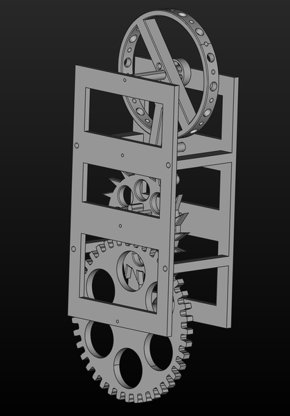
< 2023-09-17 2023-09-19 >I modeled some frame plates for the lever escapement prototype:
Annoyingly they're slightly too big to fit both on the printer at once, so I have to do 2 separate prints.
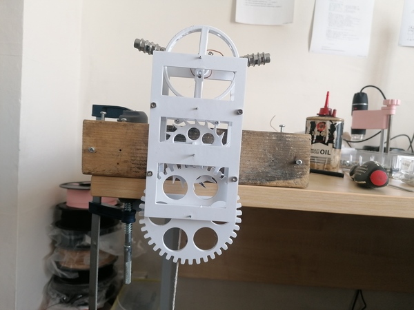
First impression is that it doesn't work very well. Problems are:
I can't yet explain the first 2 problems, but the last problem is obviously just because I made the slot too wide in the CAD.
It's tempting to try to fix the pallet pin distance by just bodging the CAD, but I think I want to try and measure everything and work out what has gone wrong.
But first, the desk is way too messy, need to tidy it up...
Comparing the lever to the previous balance wheel, the spacings look pretty much the same. And obviously in CAD they look the same. And the hole spacings on the frames are the same as well. So not really clear what the problem is. Maybe have to review the video footage.
The plan is to make a fixture to mount the metal balance wheel on the 4th axis, and then drill holes around the perimeter to allow M1.6 screws to be added.
We said an M1.6 screw is about 0.06g, currently the balance wheel is 2.6g. The shaft is mostly a 2mm diameter steel rod, 11mm long, which should weigh maybe 0.3g? And I reckon the supports across the middle are maybe a third of the mass of the perimeter, so the perimeter is 3/4 of 2.3g = 1.7g. So to double it we'd need to add 28 M1.6 screws...
So maybe the plan is we use the M1.6 screws to hold some actual weights instead. Regardless, I'm interested to see how successful I am at putting M1.6 tapped holes around the perimeter.
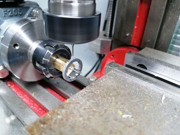
Update: instead of making a fixture I can just use the superglue arbor! Great success.
I think I want some ~25mm aluminium rod though, I don't have any material suitable for making a fixture for this. I've ordered a 60cm length.
Drilling with the 4th axis:
Tapping with the pin vice:
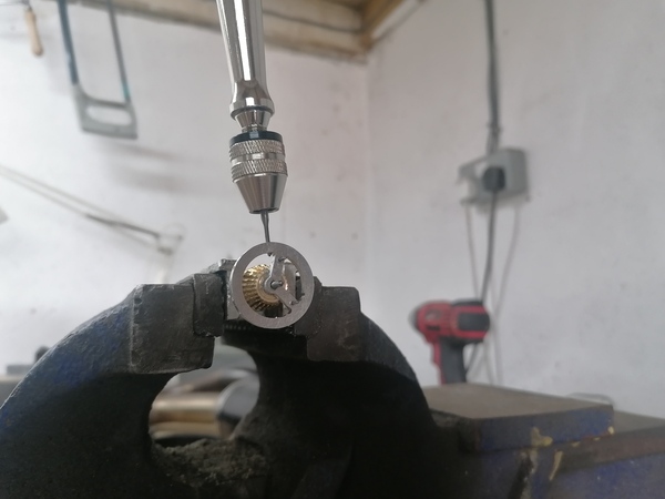
Screws installed:
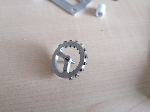
It increased from 2.6g to 3.3g (+27%), with almost all of the mass at the perimeter, so the moment of inertia should be increased by more than 27%. Still not a lot though. I can try using the M1.6 screws to hold down M3 nuts to add more weight.
With 3 nuts added it comes to 4.3g.
Bolting up the little metal frame makes it bind up a little bit, so I'm going to make some slightly-longer standoffs.
The balance wheel is too far out of balance now, so it won't run with the same weights as before, so not really possible to make a straight comparison.
Paul Mutton posted a video about a fake clipped planchet error on a 50p coin: https://www.youtube.com/watch?v=S3B3yQ6mLUo
I made the mistake of offering to make him a better fake and he has emailed me to take me up on it, so I have had to have a go. I think I did a pretty good job! Better than the example in his video at any rate.
I used a CNC router to cut the shape of a 50p out of a 50p coin:
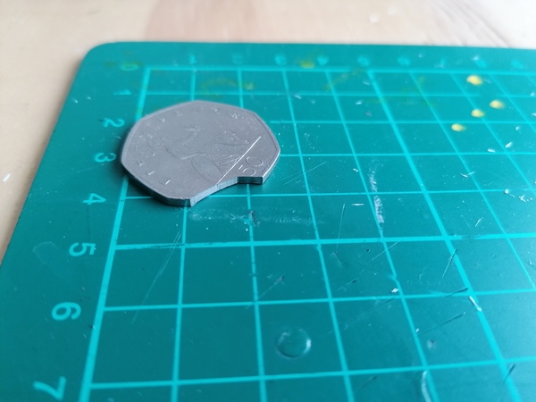
And then used a wire wheel and some polishing tools in a Dremel to make the edge look more natural:
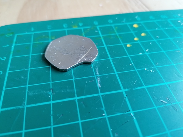
And squeezed the opposite side in a vice to create a "Blakesley effect":
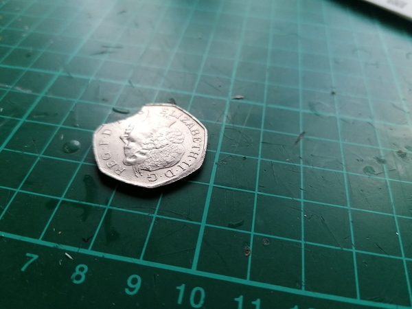
After I was finished I tried shaking it around in a box full of stones for a bit to try and age it, but I'm not sure it made a lot of difference.
I could probably do a better job of the Blakesley effect. I first tried to create it with the Dremel, which left very obvious scratch lines which remained after pressing with the vice. If I were to do another I would just press it and not use the Dremel.