If you've ever seen Robot Wars or BattleBots, you'll know what a combat robot is. An antweight combat robot is the same concept, except it has to weigh no more than 150g and fit inside a 4-inch cube. I've built one, called "Wedge of Glory", and have my first competition this weekend!
I also have a video demonstration, from before I painted the logo.
I kept a progress log as I went along on the RobotWars101 Forum, which turned out to be quite helpful as I received good feedback and ideas from other forum members.
Design
I watched quite a lot of antweight fights on YouTube (e.g. Antweight World Series 60) and noticed that a lot of the time, the robots that have big spinning weapons do more harm to themselves than to their opponents. They tend to get maybe one decent hit, and then start gyrodancing, bounce around the arena, and either self-destruct or bounce into the pit. So for a first robot, a big spinning weapon is definitely not the way to go.
I observed a few other silly ways of losing a fight, such as some robots driving themselves into the pit, and some becoming immobilised due to being upside down. It seems obvious that every robot should either be able to self-right, or even better, work upside down.
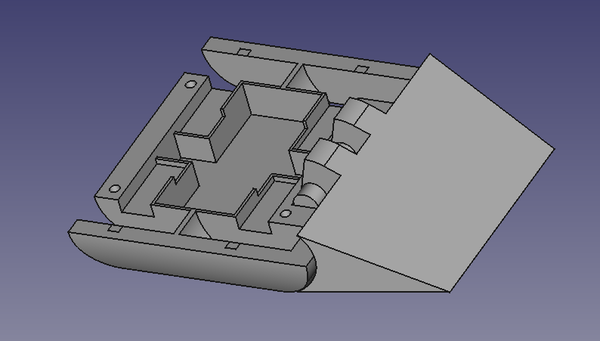
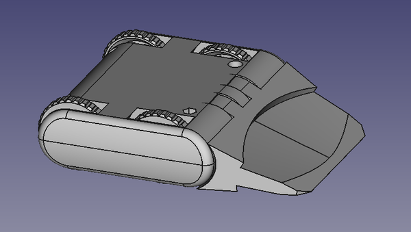
So we want a robot that doesn't have a big spinning weapon, has good control so as not to accidentally drive into the pit, and has the ability to recover if flipped upside down. For these reasons I designed a 4-wheel-drive skid-steer pushing robot that works identically when upside down. The idea is that it wins fights by pushing the other robot into the pit. Here's the CAD of the first iteration:
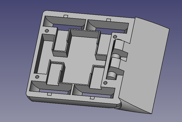
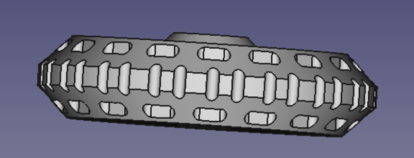
The wedge at the front is free to pivot so that when the robot is upside down it still sits on the ground. There is complete protection of the wheels on all sides. The chassis is made of 2 of these identical halves, which clamp the gear motors in place without any additional motor mounts, and the rest of the electronics just sit in the cavity in the middle.
Here it is printed in PETG to test the fit:
Electronics
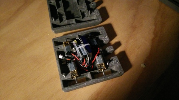
I've never done any radio-control electronics before, so I wasn't entirely sure what to buy. I ended up getting a "FlySky FS-i6" transmitter and receiver, a dual ESC from Bristol Bot Builders, a 180mAh Turnigy "nano-tech" LiPo battery, and 6v 300rpm "N20" gear motors.
In the picture above, the motors look like the ordinary motors you play with at school, but they are actually only 12mm in diameter.
All of the wiring has silicone insulation. This seems to be common in RC applications, and both the battery and ESC came with silicone wires already fitted. Unfortunately the battery connector on the ESC was not the same as on the battery, so I cut it off and replaced it with a match for the battery one. It's known as a "Losi Micro" or "Walkera" 2-pin connector. The most convenient way I could purchase these was as loose connectors and pins that you have to crimp onto wires yourself. I've tried to crimp ordinary 2.54mm JST connectors before and have literally never succeeded, and these are even smaller, so this time I cut the crimping part of the pins off and soldered the wires on instead, and then pushed the soldered pins into the connector housing. This worked much better, and I recommend it. It is true that in theory you can get a stronger connection by crimping because then the insulation is held in addition to the conductor. But in practice, an average solder joint is stronger than an average DIY crimp attempt.
The receiver is designed to have 3-pin servo plugs connect to it, but these take up quite a lot of space and weight, so I trimmed the pins down and soldered wires directly. The receiver, battery, and ESC are then cable-tied together into a single package that sits in the centre of the robot. It's a 2.4GHz receiver using a digital mode, which means you have to pair the receiver to the transmitter. This is new to me, last time I had any RC toys they were "paired" by physically switching crystals around, and you had to ensure that you didn't use the same frequency as anyone else in the immediate vicinity. The digital mode seems to be a great improvement.
Taulman 910
I bought a spool of Taulman Nylon "Alloy 910" from 3dfilaprint. This is a very strong and slightly flexible nylon filament designed for engineering applications. There is a video of a man splitting a block of wood apart with a chisel printed in Taulman 910, and I have also reproduced this result. Quite impressive stuff. (Admittedly, I haven't tried it with PLA or PETG, so maybe that would work too, but I expect the PLA would just shatter when you hit it with the hammer).
I wasn't sure whether I'd be able to print it or not, but I still had PETG as a fallback, and it turns out that Taulman 910 prints very nicely. I hope to use it a lot more.
I am printing it on an Anycubic i3 Mega, which has an "Ultrabase" build plate. It sticks well with the bed at 45°C, which is how I use it, but it doesn't release very easily after the print is done. That's a tradeoff I'm happy with, particularly in consideration of the fact that nylon is very prone to warping during printing if it is not stuck to the bed well enough. I initially tried it with the bed hotter and it kept peeling up and warping.
Taulman suggest printing it at 250-255°C. I'm printing it at 245°C and it seems fine. Perhaps layer adhesion would be better at higher temperatures, but overhang performance is worse.
It is of utmost importance that nylon filament is dry. It wicks moisture out of the air, which causes reduced strength and poor print quality. It can be dried by leaving it in the oven overnight at 80°C, and I found that it degrades significantly after less than a day exposed to the air. For this reason I have created a small drybox which allows me to print the filament without exposing it to a moist atmosphere:
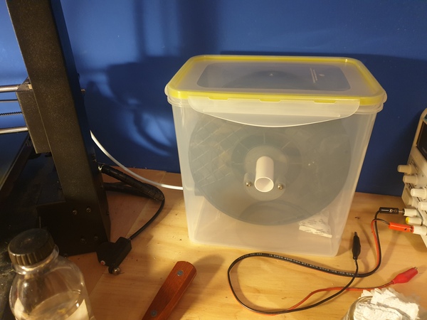
It's just a food storage box with a spool-holding spindle and a PTFE tube running to the printer for the filament to go down. Currently I just have a packet of silica gel in there, but I have ordered some loose silica gel beads that change colour when they can no longer absorb moisture, which I'll leave loose in the bottom.
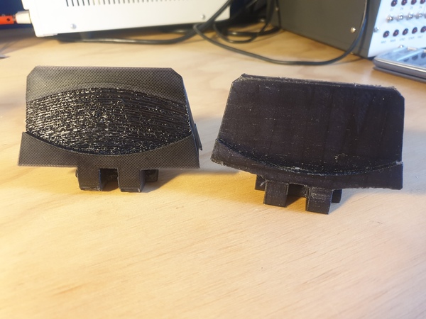
Unfortunately most of the robot parts were printed before I had made the drybox, here's a comparison between dry filament (left) and moist-ish filament (right) both printed with identical GCode:
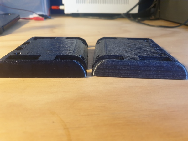
In addition to improved print quality, the part printed with dry filament is noticeably stiffer.
Wheels
The first suggestion I got was to remove the wheel protection from the back of the robot so that if the front of the robot gets lifted up, it still has some grip from the rear wheels. This is a great idea, and also reduces the amount of space and weight taken up by the chassis.
A pushing robot lives and dies by its pushing ability, so I wanted some nice grippy wheels. I bought some 2-part liquid silicone rubber off eBay, and 3d printed wheel hubs and tyre moulds. The hubs have holes running through them so that the silicone is mechanically attached to the wheel, to prevent the tyre from falling off.
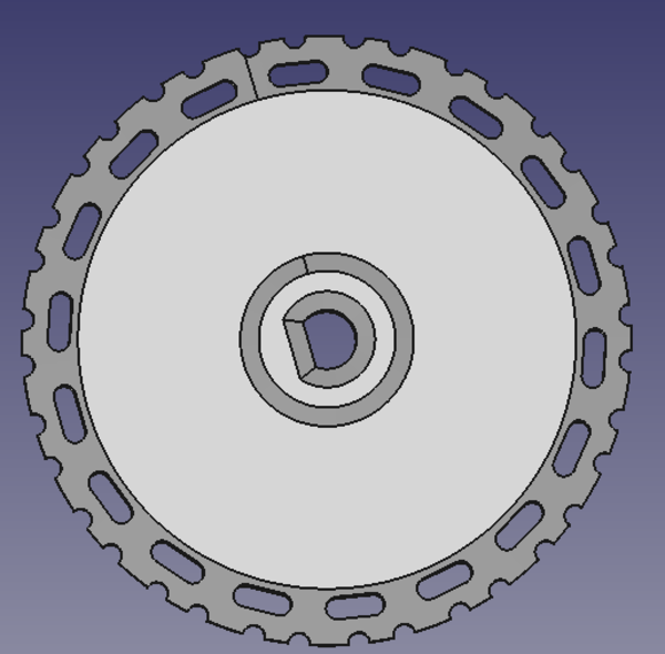
With the hub placed inside the mould, silicone is poured in and allowed to cure, at which time the mould is removed and you just have to clean up the flashing and you're left with a nuce grippy tyre moulded on to the hub. I did a test piece with a smooth tyre first:
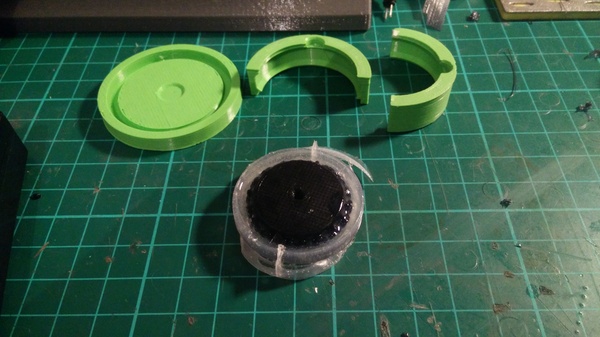
I found that in liquid form, despite its apparent viscosity, the silicone was able to seep through the cracks in the mould and I lost quite a bit of it. For the real tyres, I sealed up the mould with hot glue before pouring the silicone, and also made sure to pour plenty:
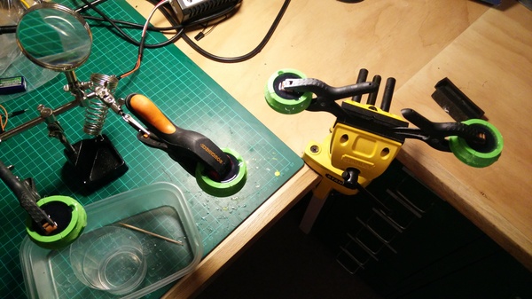
This did the trick, and I got 4 nice grippy tyres. The clamps are there to prevent the hub from floating, as the (mostly hollow) hubs are less dense than the silicone.
Wedge
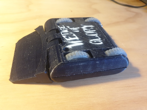
The initial wedge design came with a risk of other robots driving straight over the top, which is not what we want. To solve this, I cut a step into the wedge so that once it has lifted the other robot off its wheels, it has half a chance of catching it and pushing it along.
All installed on the robot, we get this:

Although I wasn't very happy with the surface finish on the underside of the wedge. To solve this, I printed it pointing straight upwards (right) instead of lying flat (left), so that the step doesn't create an unsightly overhang:
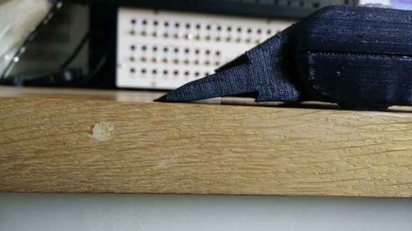
There was some concern on the forum that the wedge wasn't sharp enough to go under other robots, but I think it's fine:
4-inch cube
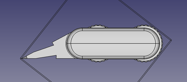
The 4-inch cube rule states that the robot must fit inside a 4-inch cube in any orientation. It needn't have its wheels touching the floor while in the cube, but it is not allowed to fit in the cube merely by virtue of being folded up, or springy. It has to fit in the same shape as that in which it will begin the fight, although it is fine to unfold later as long as this is initiated after the fight starts. For example, a flipper robot doesn't need its full flipper motion constrained by the dimensions of the cube.
My robot fits precisely across the diagonal of the 4-inch cube:
Controller
When the robot is upside down, steering still works correctly. When you steer, the left and right wheels spin in opposite directions. With the robot upside down, the wheels have moved to the opposite side, and are spinning in the opposite direction. These effects cancel out and steering still works, but forwards and backwards movement become inverted. To fix this I wanted to use one of the auxiliary switches on the controller to invert the "throttle" input so that if the robot is upside down I could simply flick the switch and continue driving as normal.
Despite the wealth of configuration options available in the FS-i6 menu, it appears that it is actually impossible to get it to invert a channel at the flick of a switch. It has a way to permanently invert a channel, and it has a way to use a switch to set a different rate on a channel, but it has no way to let you select a negative rate. Razerdave on the forum suggested a solution.
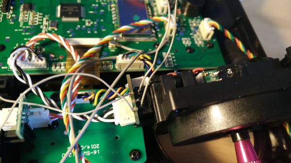
Each input axis controls one potentiometer. By cutting the connections to the potentiometer and inserting a DPDT switch in the middle, we can invert the voltages at the ends of the axis so that the transmitter thinks we've moved the joystick in the opposite direction.
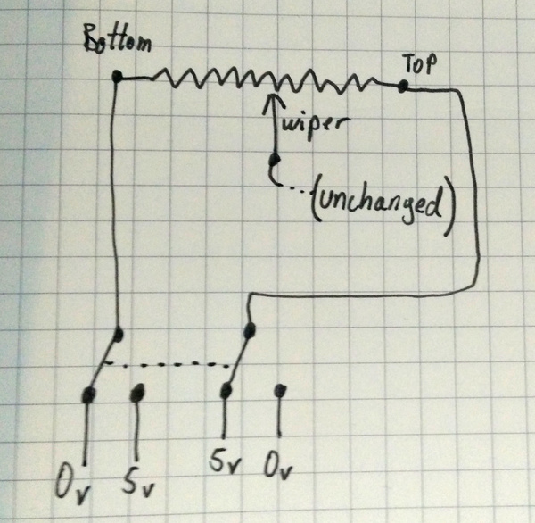
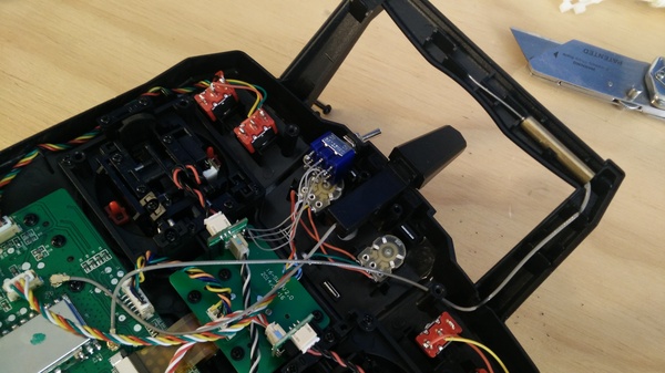
I did this by opening the controller up, finding the potentiometer that I am interested in, cutting the pins for the two ends of the potentiometer, and soldering wires in their place. By twisting the wires together first the same way as before, and then inverted, I verified that this correctly inverted the operation of the joystick. Great success!
I then drilled a hole in the case and fitted a DPDT switch to the ends of the wires:
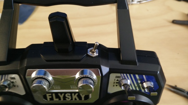
Quite a neat mod, I think.
The only surprise was that the centre position of the joystick does not exactly correspond with the centre position of the potentiometer, but usually you wouldn't notice because this is compensated in software so that the channel is at the 0 position with the joystick centred. Unfortunately, when you invert the joystick, the centre position is no longer the 0 position. I have worked around this by setting the trim on the channel so that it's close to the centre in both the forwards and reverse mode, and in both cases the error remains within the hysteresis on the ESC so the robot stays still with the stick centred.
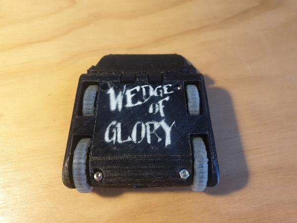
Logo
To finish the robot off, and to help me distinguish the top from the bottom, I 3d printed a stencil and spraypainted a "Wedge of Glory" logo on to one side of the chassis: