
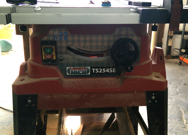
I have a Lumberjack TS254SE tablesaw. It's not a high-end tablesaw, but it was relatively cheap and it works well enough. Except for the blade tilt mechanism.
(Apologies for the awful lighting in some of these pictures.)
You can see a crank handle on the right hand side of the front of the tablesaw. Cranking the handle raises the blade up and down: this feature works fine. Rotating the wheel that the handle runs inside tilts the top of the blade between 0° and 45° to the left. The tilting feature never worked satisfactorily. Between about 0° and 15° it was fine, but beyond that the gear teeth would start skipping unless you wedge the handle sideways, and it would take progressively more effort to get the blade to tilt the further you want it to go.
It recently got so bad that I was avoiding making 45° mitres because I knew it was too much trouble to tilt the blade over.
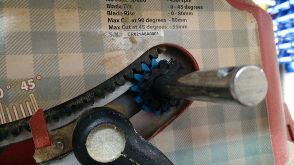
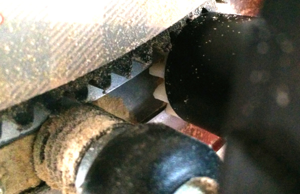
So I had a look at the mechanism. There is a curved toothed "rack" on the frame of the machine, and a pinion gear on the handle. I discovered that the gear on the handle was too small. Or, most likely, the designer deliberately spaced the gear teeth apart to stop them from binding when manufactured with sloppy tolerances, but went too far and now they don't mesh properly.
Upon taking the handle off, I discovered that not only were the teeth on the gear too small to mesh against the rack, but some of them had become partly broken due to the abuse.
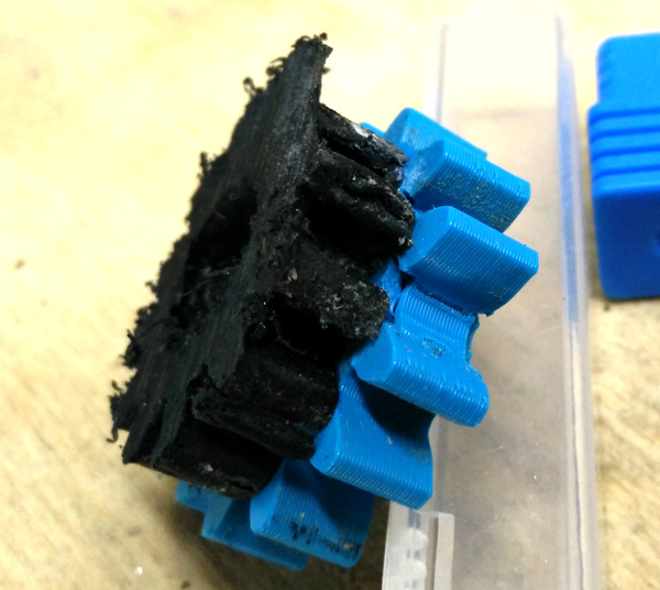
So I designed a quick test gear in FreeCAD, 3d printed a test piece in PLA, checked the mesh of the teeth, and (after getting it the correct size on the 2nd attempt) superglued it to the existing gear just to check that it worked. Which it did, but the "draft" mode PLA teeth broke quite quickly.
Having discovered the correct shape of the gear, I then had the problem of how to attach my gear to the handle. I didn't want to 3d print an entire new handle. I settled for hacksawing the original gear off the end of the handle, facing off the handle on the lathe, and then gluing a new gear to the end of the handle with epoxy. Unfortunately I hadn't taken any pictures up to this point, but here's what I was left with after hacksawing the gear off:
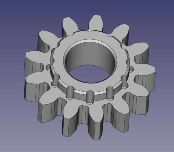
My replacement is quite a lot bigger than the original!
The 2nd picture there probably best shows how the mechanism works. The gear is not keyed to the shaft. Turning the shaft raises/lowers the blade. Turning the gear engages with the rack, which causes the shaft to be dragged left/right which causes the blade to tilt. Obviously, if the gears don't mesh properly, then you can't move the shaft left/right so you can't tilt the blade.
For the real version of the part I modelled in some holes to help the epoxy mechanically hold the gear in place:
Printed this part in Prusament PC Blend, 100% solid (it's entirely made out of perimeters, no infill), and epoxied it to the handle:
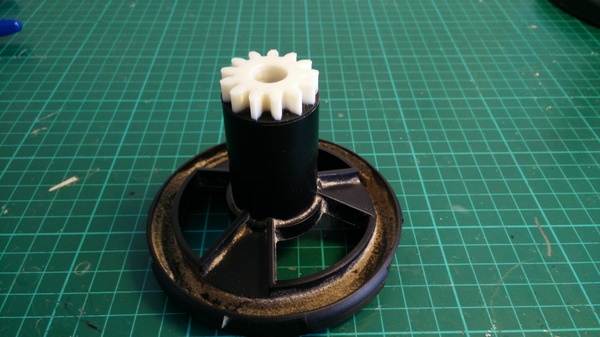
Then it's just a case of installing it on the machine:
So far it's a great success. I wish I'd done this sooner. In the event that the printed polycarbonate gear breaks I will make a replacement out of aluminium using the CNC machine.