
I've got into signed distance functions recently and am interested in their application to CAD software.
I first came across SDFs from some video demonstrations by Inigo Quilez (for example Painting a Landscape with Mathematics) and it very quickly became apparent how powerful this technique is. I don't quite have the intuition for it that he does, but thankfully he has written extensive reference documentation.
Introduction
A signed distance function is a representation of a solid object in the form of a function f(p), where p is a vector representing a point in space. The function returns the "signed distance" from the point p to the nearest point on the surface of the object, negative if p is within the object and positive if it is outside.
The surface of the object is found at f(p) = 0, this is called the isosurface.
Boundary representation
The primary representation of objects in CAD software is the boundary representation, or "B-rep" (e.g. used in FreeCAD). The boundary representation consists of keeping track of all of the points, edges, and faces that make up the object, and the connections between them, and writing lots of complicated geometry code to deal with all the edge cases that come up when you try to combine primitives in interesting ways.
Edge cases in the boundary representation are the reason that FreeCAD sometimes crashes if you try to do things like complicated fillets. Boundary representation gets very complicated very quickly.
SDFs are cool because arbitrarily-complicated shapes combine with basically zero edge cases, and you can define functions that do cool things like texturing arbitrary surfaces. And it all takes a really tiny amount of code.
And some operations which in traditional CAD get really expensive due to overlapping boolean operations taking quadratic time (like a PolarPattern with 200 occurrences) can be done almost instantly with SDFs.
Example
float sdSphere(vec3 p, float r) {
    return length(p)-r;
}
This is the SDF for a sphere centered on the origin with radius r. The distance from a point p to the surface of a sphere is the distance of the point p from the origin (i.e. the length of p) minus the radius of the sphere. Satisfy yourself that this equals 0 for points on the surface of the sphere, is less than 0 for points on the inside of the sphere, and is greater than 0 for points outside the sphere.
Let's say you don't want your sphere at the origin, you want it at some other point q.
You could try:
float sdSphereAtPoint(vec3 p, vec3 q, float r) {
    return length(p-q)-r;
}
Which is not too hard, but I thought we said we can operate easily on arbitrarily-complicated shapes? You don't want to have to add a q parameter to every single function just to move things away from the origin.
To translate an arbitrary SDF f(p) by a vector q, you need to evaluate f(p-q).
Another interesting one is:
float sdUnion(float d1, float d2) {
    return min(d1, d2);
}
Boolean union is just min()! The distance from a point to the surface of the union is the closest of the distances between the point and the individual objects.
Intersection is max().
Subtraction is max(d1, -d2), i.e. the intersection of shape 1 with the inverse of shape 2 (-d2 swaps the interior and exterior of the shape - yes the shape will then have an infinite volume, this is also not a problem for SDFs).
And with these functions plus some primitives, we have an SDF implementation of Constructive solid geometry.
And then when SDFs start to get really cool is with operations like "smooth minimum", this is a family of functions that act like a boolean union, except with automatic smoothing of the join. An example is:
float smin(float a, float b, float k) {
    float r = exp2(-a/k) + exp2(-b/k);
    return -k*log2(r);
}
For points far away from the join it returns about the same as min(), but near the intersection it gives smaller values, so that the join "grows outwards" and looks smooth, like this:
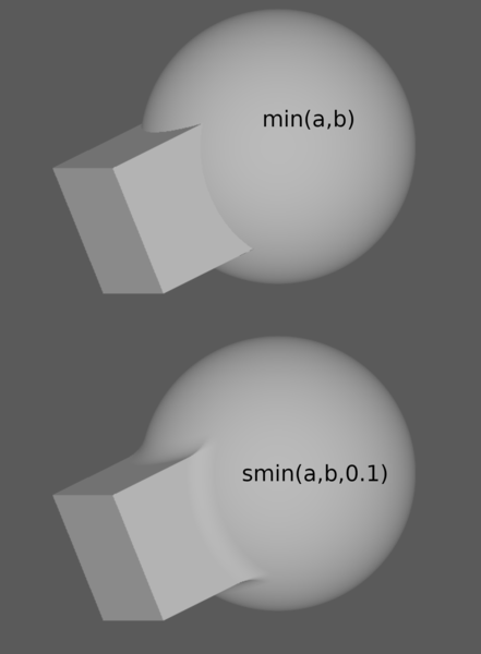
So we're already filleting edges with basically no code at all!
For comparison, the chamfering and filleting module in OpenCascade (FreeCAD's CAD kernel) is over 36,000 lines of code.
(I grant that FreeCAD lets you target your fillets and chamfers more precisely, whereas smin() is kind of a blunt instrument).
I said that patterns with high number of occurrences are slow with B-reps but didn't say why they're fast with SDFs:
Even straightforwardly doing patterns with unions would be an improvement with SDFs because it is linear in the number of copies instead of quadratic, and you can potentially do it in constant time with domain repetition, which is where you map the coordinate system down to the range that covers just one object (for example to repeat your object every 10 mm in the X axis, make your X coordinate repeat every 10 mm, bounded to the number of copies required).
Domain repetition is trivial for non-overlapping copies, but what about overlapping ones? If you have a known bounding volume I think you could use the same technique, for example by making 100 domain repetitions of a union of only 2. At that point it is linear in the number of overlapping bounding volumes rather than the total number of copies.
Rendering
OK, so we can define an object and do our CAD operations on it, but the representation is still only in our minds at this point. How do we put a picture on the screen?
The best answer is ray marching in a GPU shader. I know that "ray marching" sets off alarm bells saying "wow, that sounds super computationally expensive". But it's not, for one really cool reason!
The SDF tells you how far you are from the isosurface! So instead of having to march your ray forwards at miniscule increments to ensure you don't step over the model without noticing it, you can jump forward from every point p by a step of size f(p) and know that you will never miss anything! So in practice the ray marching either diverges quickly (i.e. rapidly gets further away from your part as it accelerates away into the void), or converges quickly (rapidly approaches the surface as it jumps forwards by steps equal to the current distance to the closest point).
This picture from Wikipedia shows the principle:
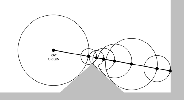
The circles represent the value returned by the SDF (distance to the closest point), and you can see the step size slows down as the ray gets close to the surface, and speeds up as it gets further away.
Meshing
OK, so we can draw the object on the screen. How do we 3d print it?
Marching cubes is an algorithm for turning an isosurface into a triangle mesh. We'll use marching cubes to create an STL file of the object and then slice it with whatever normal slicing software and 3d print as normal.
Prior art
I'm obviously not the first person to think of using SDFs for CAD software.
Existing projects include:
And these all have one thing in common: you have to design your model in code, instead of a traditional CAD user interface. I've used OpenSCAD enough to know that this is not what I'm looking for.
Another interesting project to look at is Fornjot, they have an article Why Fornjot is Using Boundary Representation that discusses the issues with using SDFs for CAD. That article was over 2 years ago and Fornjot is still an "early-stage b-rep CAD kernel", which doesn't exactly refute my point that boundary representation is really complicated.
And as far as I can see Fornjot doesn't have any user interface either.
Why Fornjot is Using Boundary Representation
But let's not let a cautionary tale go to waste! What are the reasons Fornjot moved away from SDFs?
1. Common operations don't result in a correct SDF
I lied earlier. When I said the SDF of the union of 2 SDFs is just min(a,b), that was a lie.
The property that makes SDFs work really well is what I'm calling "the distance property". That is the property that every point in space evaluates to the true distance from that point to the isosurface.
And boolean operations don't preserve the distance property!
The boolean operations do however preserve a different property which is almost as useful. They give you a function which is a lower bound on the distance from p to the isosurface. That means ray marching still works, because it is always safe to step forward by a distance f(p) without missing any geometry.
Sometimes you actually do need the distance property. For example if you want to expand your object by some fixed thickness th:
float sdExpand(d, th) {
    return d-th;
}
If the distance is wrong, the expansion will be wrong.
Depending on the reason the distance is wrong, it might be possible to "renormalise" by dividing the distance by the length of its gradient. I.e. sample the SDF at a few other places nearby, and if it looks like the distance is changing by 3x as much as it should be for the distance away you sampled it, then divide the distance by 3. But that won't always help (erm... excuse me, I was told there would not be edge cases??).
Inigo Quilez has more on this topic.
2. CSG is not enough
This is true. CSG is not enough.
But SDFs aren't limited to CSG! I don't see how this is a critique of SDFs.
The "draw a sketch, pad/pocket/revolve, draw a sketch, pad/pocket/revolve" workflow (that I find to be the most productive CAD workflow) is possible with SDFs! And in fact it's a really good fit for SDFs.
We just admitted that boolean operations break the distance property and that we don't like that. But do you know what doesn't break the distance property, and in fact has an analytical solution?
That's right! Drawing a sketch and then padding/revolving it! (Not pocketing, sorry).
Quilez has example code showing the implementation of a 2d SDF for a shape made out of line and arc segments (scroll down to sdShape() on that shadertoy).
(That covers approximately 100% of the sketches I make in FreeCAD. The remaining ~0% also need B-splines, but I read that there is an analytical 2d SDF for quadratic Bezier curves. I'd just need to find an LLM that can program the mathematics for me.)
And he also has example code for padding and revolving, see opExtrusion() and opRevolution() on his extensive 3d SDFs page.
Inigo Quilez has basically solved all the mathematical problems with SDF-based modelling, and published the solutions in a form that is easy for programmers to read and understand. His site is a superb resource. I ought to take a mirror of it just in case it ever disappears.
3. Marching cubes doesn't work very well
The drawback cited on the Fornjot blog is that available algorithms aren't very good "in terms of how well the generated triangles match the original geometry", or are crazy complicated.
I'm not going to bother addressing "crazy complicated" because that is obviously not what I'm looking for. What about not matching the original geometry?
I want to use CAD so that I can turn my ideas into 3d prints. So, firstly, if the triangle mesh matches the original geometry to a precision better than I can 3d print, it may as well be flawless. And secondly, you can tune mesh precision at the cost of mere computational expense. It takes hours to 3d print most objects, if it takes 30 seconds to generate a triangle mesh at the required precision, I can live with that.
(I don't know that it will take that long, I'm just making the point).
Perhaps they thought this was a problem because they were rendering the SDF on screen by turning it into a triangle mesh first? Judging by the screenshots, sdfx does the same thing:
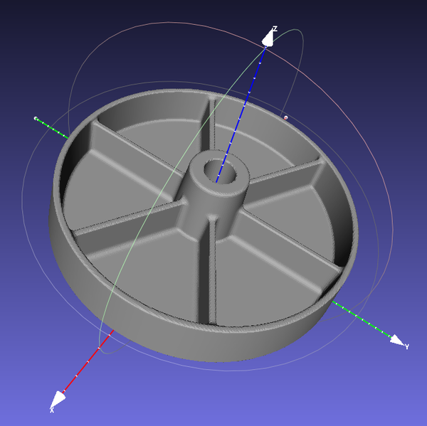
I agree that if you are rendering the model from a triangle mesh then, yes, of course you need a really high quality mesh, and you need it created really fast. But given that ray marching in a shader exists and is easy to do, I just don't see why you would render the model as a triangle mesh? (Maybe I'll find out the hard way when I start making more complicated models).
Isoform
If you read this far you may have guessed where this is going.
Cursor and I are working on an SDF-based CAD program.
You can try it out now if you want, it's called Isoform. It runs in the browser. And it fact it has no dependencies and it is fine to just clone the github repo and run it locally. I think more web apps should be "local-first" in this way.
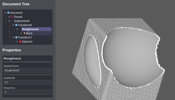
It is super early days (so far only a bit over 2000 lines of JavaScript) and I see it more as an experimental project than a serious CAD application. I definitely don't have ambitions anywhere near as large as FreeCAD, I'm aiming more along the lines of SolveSpace. But it's not there yet, I definitely don't recommend actually trying to use it for anything, but just have a play if you're interested. You need to right click in the tree view to do anything. I'm particularly interested in hearing from you if you managed to get it to do anything, or if you tried it and it didn't work.
The edge detection feature (highlighting edges in white, see screenshot above) is based on finding sharp changes in the surface normal. I'm not really happy with it, I just did it to see how viable my idea for detecting edges is. This is an area where B-reps have an obvious advantage, because they already know the list of edges, no need to detect them!
The texture on the surface is implemented by permuting the child object's distance by some random-ish sine waves. This is an example of an operation that flagrantly breaks the distance property, but is worth having anyway because it lets you do really cool things. In fact this operation also breaks the "lower-bound" property. About the only property it maintains is that f(p) = 0 defines the surface. And that's more just a property of what it means to be an isosurface...
But texturing is cool anyway, and I don't think it matters if your finished object has a broken SDF. The goal is not a mathematically-elegant description of your thing. The goal is a 3d-printed part, and any unpleasantness in your broken distance function is forgotten as soon as you turn it into a mesh.
Implemented:
- box/sphere/torus/cylinder primitives
- union/intersection/subtraction operations
- roughness modifier (really just a proof-of-concept for texturing; real texturing operations would work similarly but look better)
- CAD-friendly UI with tree view and property editor
I plan to implement:
- the "draw a sketch and pad/pocket/revolve" workflow
- linear pattern, polar pattern, mirror
- more primitives
- more cool texture modifiers, like "Roughness" in the screenshot
- taking datum points/lines/planes off the existing model
- targeted fillets/chamfers (currently you have to do it with a combination of the "roundRadius" property on the primitive, and the "smoothK" property on the combinator), I plan to figure out a way to localise a fillet/chamfer to a datum line, and then you get to target fillets like in big boy's CAD programs
- exporting a mesh
- importing a mesh (maybe; not sure this is a good idea - the SDF of a mesh would be enormous)
- saving your work
- isomorphism between the tree view and an OpenSCAD-like representation
Conclusion
I hope I've convinced you that SDFs are a promising alternative to traditional boundary representation modelling. For some applications SDFs win out because of their simplicity, efficiency, and robustness. We should focus on the advantages and not worry too much about the drawbacks. I read that any art medium's most painful flaw turns out to be its most defining signature, and currently we have far too many parts with B-rep flaws and not nearly enough with SDF flaws!
And obviously many thanks to Inigo Quilez for doing all the hard work and for documenting it so well.