
I recently came across the RC2014. It is a simple computer sold in kit form, and using a Zilog Z80 CPU.
I understand that 2014 is the year it was designed, and "RC" stands for "retro computer".
What is it?
The RC2014 website says:
RC2014 is a simple 8 bit Z80 based modular computer originally built to run Microsoft BASIC. It is inspired by the home built computers of the late 70s and computer revolution of the early 80s. It is not a clone of anything specific, but there are suggestions of the ZX81, UK101, S100, Superboard II and Apple I in here. It nominally has 8K ROM, 32K RAM, runs at 7.3728MHz and communicates over serial at 115,200 baud.
Being a "modular" computer means that the RC2014 uses a backplane system that various modules can be plugged into. A backplane is essentially a motherboard that has no components on it: all it does is connect the modules together. The CPU has no special place, it's just another module connected to the bus. I have found playing with the RC2014 has given me a much better understanding of how a CPU actually interacts with the other elements of a computer.
For convenience of hobbyist use, the RC2014 uses 0.1" pin headers to plug into the backplane, rather than the more common card edge connector used by S-100, ISA, PCI, etc.
The standard backplane has 40 pins, of which 4 are unassigned and can be used for whatever you want. The "enhanced" backplane has an additional 20 pins, incorporating a handful of CPU lines that were missing from the original bus, an additional 8 pins of data bus for potential expansion to 16-bit CPUs, and 4 more unassigned pins.
As far as I'm aware, it's not possible to buy a fully-assembled RC2014, they are only available in kit form.
Building the kit
The RC2014 kits, and various upgrade modules, are available from the RFC2795 Ltd Tindie Store, and there are also various other modules available from other sellers, including "single-board computer" variants, a video card, various storage modules, and also other CPU options, including the Z180 and the 6502.
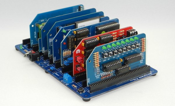
I chose the all-singing all-dancing "Zed Pro" variant of the official kit, which comes with a 12-slot "enhanced" backplane, 512K ROM, 512K RAM, dual clocks, and dual serial ports.
It's quite a bear to solder up. Even though not all of the "enhanced" slots have the headers installed, the backplane sockets alone are 5*60 + 7*40 = 580 solder joints. Then you have a corresponding 40+ pins per card for the backplane plug, 40 pins each for CPU, ROM, RAM, and serial controller, and 13 other 14- and 16-pin ICs. That's already over 1000 pins, and there are more headers, resistors, capacitors, etc. still to count. It took me many hours over 2 sittings to finish soldering up what I've got so far. And I still have more to acquire!
If you're playing along at home, I'd recommend taking the time to make sure the pin headers and IC sockets are properly seated against the board. I like to solder just one pin at first, and then push the part down with my finger while I re-melt the solder, to make sure it sits nice and flat. If you solder all 40 pins and then decide you don't like the angle it's mounted at, you'll have a tough job fixing it.
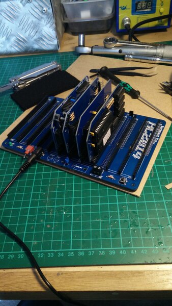
When I'd finished, I only had 1 resistor left over, and the machine seems to run OK so it can't have been an important one.
With the parts assembled, it's just a case of plugging a USB FTDI cable into a serial port header, switching the machine on, hitting the reset button, and then interacting with it over the USB serial cable. I understand that the dual clock module has a power-on reset function, so that it can automatically reset the CPU when power is applied, but I am not entirely sure how it is meant to work, or whether I have not enabled it, so for now I need to manually reset it every time I switch it on.
Memory
The Z80 has a 16-bit address bus and therefore only 64K of address space, so what's the use in having 512K of RAM?
It is possible to use bank switching to map different parts of the 512K into the 64K address space at any given time. Note that this is not a CPU feature! The CPU neither knows nor cares about the memory layout. The CPU just puts addresses on the bus and the memory hardware does whatever it wants. The software tells the memory hardware to change the bank by writing to an I/O port. On the RC2014, this is implemented with just 5 TTL chips.
I couldn't find a schematic or explanation for the "official" RC2014 bank switching, but Scott Baker's blog has a well-documented example of a bank-switching implementation (as well as many other excellent RC2014-related resources):
Writing to the bank select port clocks D0 and D1 into a pair of flipflops on a 74HC84N. The RC2014’s RESET pin is connected to the clear pin of the flipflops, so that a reset will always reset the flipflops back to zero. This allows us to write any of four values — 0, 1, 2, or 3 — to the flipflops and will serve as our bank select. The default is zero.
(D0 and D1 are the least significant bits of the data bus).
The 512K ROM module came with RomWBW flashed on it. RomWBW includes a built-in boot monitor, as well as a bundled copy of CP/M. When booting CP/M from RomWBW, it comes up with a 384K RAM disk and a 384K ROM disk with some useful programs on it. RomWBW is quite a convenient way to get a working CP/M system without needing a "real" storage device.
CP/M
CP/M is an extremely simple operating system. It only has support for single-tasking, and while your program is running it has complete control of the entire machine.
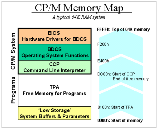
There is a great page about CP/M Internals on the Obsolescence Guaranteed website, but the summary is that the OS is composed of the BIOS (basic input/output system), BDOS (basic disk operating system), and CCP (console command processor). The BIOS has to be customised to match the hardware, and present a standardised view of it to the rest of the system. The BDOS provides higher-level functions for file manipulation, and the CCP provides a user interface. When a program is executed using the CCP, it is loaded into the TPA (transient program area), starting at 0x100 (256 bytes), and then executes from there. The lower 256 bytes include jump vectors to access the BDOS and BIOS functions, as well as the contents of the command line arguments and various other stuff that wants to be at a standardised address. The BIOS, BDOS, and CCP live at the top of memory, so that the large chunk in the middle is available for the TPA. There is a total of 41 system calls.
The standard CP/M text editor is called ED. It seems to work a little bit like the eponymous Unix text editor, but with different syntax. I still haven't quite got a good mental model of how to correctly use it, but I've got to the point where I can stick some characters in a file in the order I desire, and then rearrange them later. But I still find the editor very clunky, and I'd like to get better at using it.
Having written an assembly language program in ED and stored it in the RAM disk at (say) A:HELLO.ASM, we need to assemble it using the ASM program. I followed Jeff Tranter's instructions and got my hello world program assembled. The ASM program produces HELLO.PRN and HELLO.HEX files, but surprisingly does not produce HELLO.COM which is the one we'd want if we wanted to execute the program. I don't know why. HELLO.PRN contains our original assembly language source code, but annotated on the left hand side with a hex listing of the generated machine code. HELLO.HEX contains the generated machine code in Intel HEX format.
Since we actually do want to execute the program, we need to get hold of HELLO.COM. Fortunately, the LOAD program can do this for us. LOAD reads the HELLO.HEX file and produces HELLO.COM, which we can then execute.
Another interesting program is SAVE, which is used to save the contents of the TPA to the disk. I'm not quite sure when you'd want to do this, but you can do some funny things with it. For example if you write a program in MBASIC, and then return to the CCP, you can save the contents of the TPA to disk in a new .COM file, and then when you execute that new .COM file, you'll be back in MBASIC, but your BASIC source code will be in memory already, because it was in the memory that you saved. Presumably this won't work against anything that dynamically initialises its memory contents when it starts up.
There is lots of documentation available in the CP/M manual, but much of it is confusing.
I originally got the 512K RAM module so that I'd have a chance of running FUZIX, a Unix-like OS for 8-bit computers. FUZIX uses bank switching to provide context switching, with one process per bank of memory. I initially looked down on CP/M as a primitive and uninteresting operating system, but it's actually fun to learn about such a simple way of working, and I'm enjoying CP/M so much that I probably won't bother with FUZIX for a little while.
VGA Console
Having to use the RC2014 over an FTDI cable connected to a modern computer weakens the experience somewhat. From the user perspective, it's no different to simply running CP/M in an emulator. For that reason I want to get the RC2014 to talk to a keyboard and a display itself. The serial ports are exposed on the backplane, so it's quite easy to plug in another card that can provide a serial terminal, without any software changes required.
The recommended way to do this is to use a Raspberry Pi Zero card, mounted in one of the backplane slots, to provide a serial terminal.
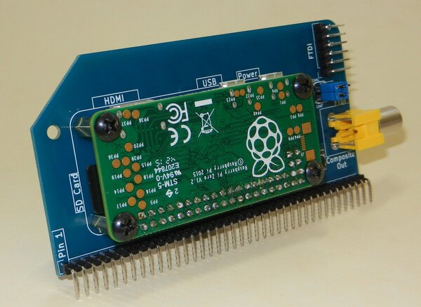
But that idea didn't really satisfy me. A Raspberry Pi is a computer in its own right, and is substantially more powerful than an RC2014. It still feels a bit too close to just using an emulator.
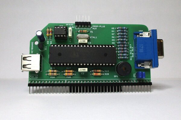
My favourite option is Marco Maccaferri's VGA serial terminal. It takes a USB keyboard for input and provides an 80x25 character console on the VGA output, using a Parallax Propeller microcontroller. Now, granted, a Parallax Propeller is also substantially more powerful than an RC2014, but importantly it isn't a computer, and it comes in a through-hole package so it doesn't spoil the aesthetic.
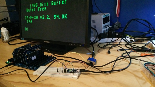
Unfortunately, Marco's VGA serial terminal was out of stock when I wanted to get one, so I tried to recreate it using an Arduino. I'd already seen Ben Eater's World's Worst Video Card project, so I understood that it was possible to bit-bang a VGA signal, and I found Sandro Maffiodo's VGAX library already implemented all the hard parts. Unfortunately, the Arduino is not really fast enough, so the library only allows for 120 pixels of horizontal resolution.
Also, the framebuffer at 120x60 and 2 bits-per-pixel takes up 1800 bytes of RAM. The Arduino only has 2048 bytes in total, and that doesn't leave enough remaining for the character buffer and stack variables. But I only needed black and white, so I modified the library to only use 1 bit per pixel, and managed to get it working as a 19x10 character display:
The wiring is remarkably simple. 3 pins of the Arduino are connected through resistors to 3 pins of the VGA plug on the screen (hsync, vsync, and the green channel), and the TX line from the RC2014 bus is connected to the RX pin of the Arduino, so that the Arduino reads the serial output from the RC2014.
But 19x10 characters is really not enough to be going on with, and I'd still have to figure out how to provide keyboard input. And thankfully Marco's VGA serial terminal is back in stock and I now have one on order, so I won't have to bother.
Front Panel
One of the coolest parts about old computers was the front panel. Two iconic examples include the Altair 8800 and IMSAI 8080:
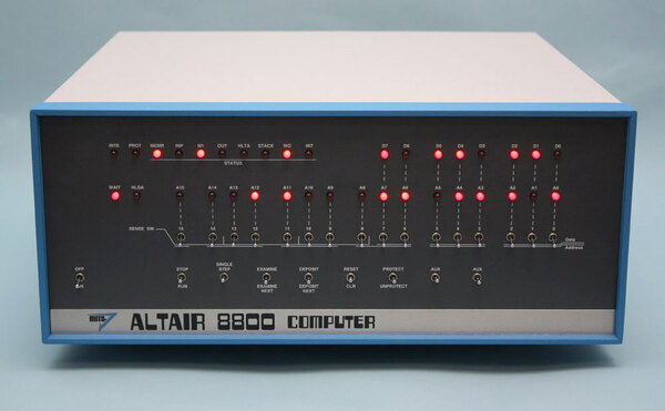
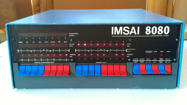
The switches and lights on the front panel act as a crude debugger, allowing the user to pause execution, single step through instructions, and view and alter the contents of memory. Additionally, on machines with no ROM, the front panel is the only way to get any code to execute after a cold boot, even if it's just a minimal bootloader for an OS on disk.
So I want to make a front panel for the RC2014.
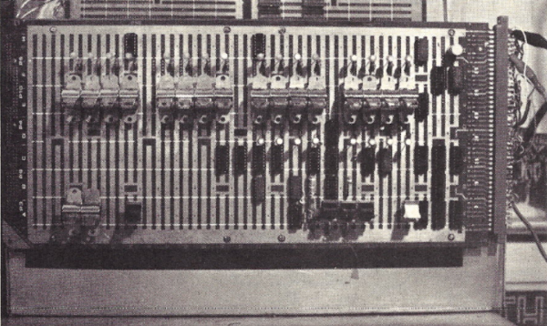
As it happens there's an excellent article in the June 1978 issue of Kilobaud Magazine on just such a project: "Home-Brew Z-80 System Part 1: front-panel construction". It's about how to make a homemade front panel for a Z80 on an S-100 bus, but it's not too far away from an RC2014. I'm not quite good enough at electronics to understand how it works yet, but I think it should be doable.
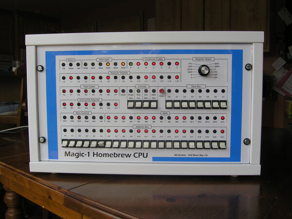
Another good example of a homemade front panel is the one on the Magic-1 Homebrew CPU:
Storage and networking
I'd obviously like to get some sort of permanent storage. A CompactFlash card is the cheap and easy option, but a more authentic experience would be dual floppy drives.
And I'd like to find a way to get this thing connected to the Internet, and maybe host a small website on it. Graham suggested using SLIP to connect it to another computer over the second serial port, which is probably the easiest way to go. Another option would be to use a WIZnet W5500S2E-R1 ethernet module or similar, and do away with the requirement for a "host" computer.