
I made a loaded die with a tiny servo hidden inside that can move the weight around to change the distribution of roll probabilities.
Design
A few months ago, Ruari had the idea of making a hollow die with a magnet under each face and a ball bearing inside. Using a larger magnet external to the die, you would attract the ball bearing to whichever face you wanted to be heaviest, and therefore make an adjustable loaded die. I did some experiments with that idea but I couldn't get an external magnet to be strong enough to move the ball around, and I couldn't stop the ball from moving around on its own when shaken.
I got this tiny linear servo off eBay:
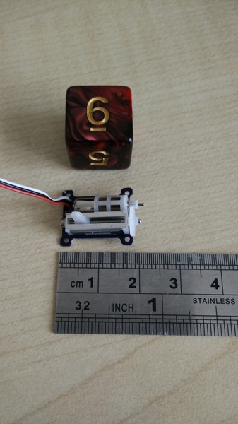
At 20 mm long, it is only slightly larger than a typical d6.
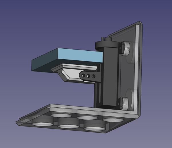
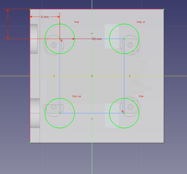
I modelled a die, split into 2 parts, which I could mount the servo inside:
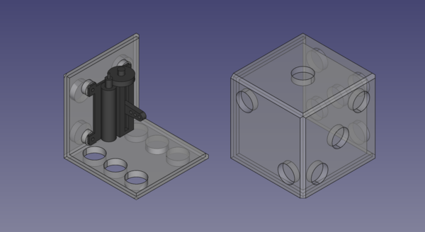
Three of the holes on the face with number 6 go all the way through. This will be useful later.
I also designed a small platform to mount on the servo horn, to carry the weight:
Build
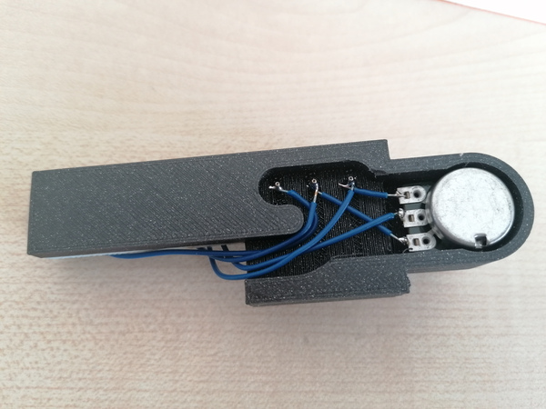
With the parts printed out and assembled, and 3 short brass rods turned on the lathe, we get this:
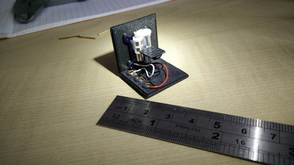
So perhaps now you see how it works. The 3 wires that control the servo are soldered to the back of 3 of the brass pips.
At this point I realised that with the weight mounted on top of the platform, I would be able to drive it all the way to the face with number 1, but not really get it very close to the face with number 6. I want to be able to roll 6's on command, so obviously this needs to be the other way around. Right?
So I put the platform on the other way up before gluing the steel rectangle to it. Now the weight can get very close to the 6 face. Great success?
Except that's the opposite of what I want! If I want to roll 6's, then I need the weight to be opposite the 6, so that the 6 faces up when the weight is at the bottom. So it was right in the first place. D'oh! But with the platform upside down, the steel ends up not centered on the platform, so I can't put the platform back where it was else the steel won't fit inside the cube. Oh well. I'll just have to roll 1's on command instead of 6's.
At this point I lamented that the brass rods were taking too long to make on the lathe, and Dimitris suggested cutting them out of brass sheet on the CNC machine. I don't know why this didn't occur to me before, but it's much quicker. I cut out the remaining circles and glued them into the remaining spots for pips:
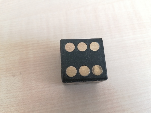
I realised another blunder at this point, which is that I managed to stick the pips for the 4 off-centre:
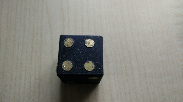
This is because I centered the pips on the origin in CAD, but the face was not centered on the origin, so the pips are not centered on the face:
Never mind.
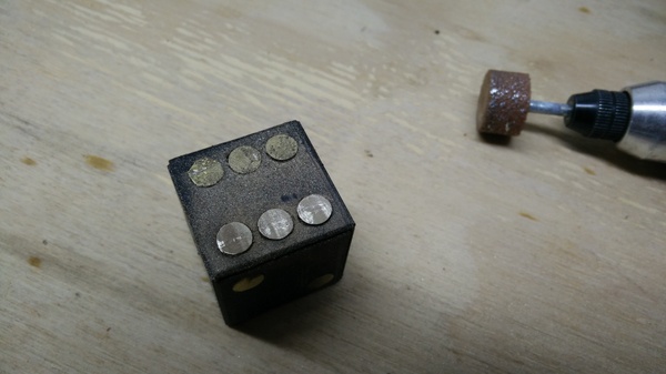
Now it's time to tidy up the faces to make them look a bit neater, starting with the pips that connect to the servo, because they stick out the most:
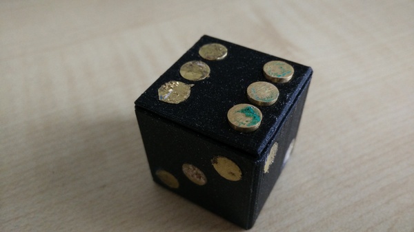
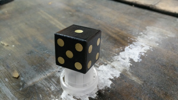
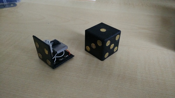
And finally, after some sanding and clearcoat, we have this:
Which I'm quite happy with.
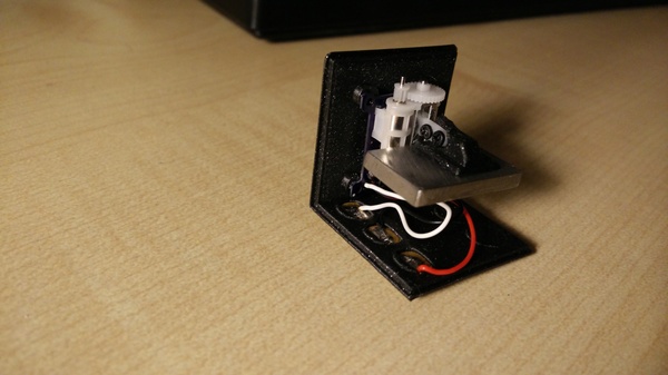
Cradle
Now we need a cradle to hold the die in to connect to the conductive pips.
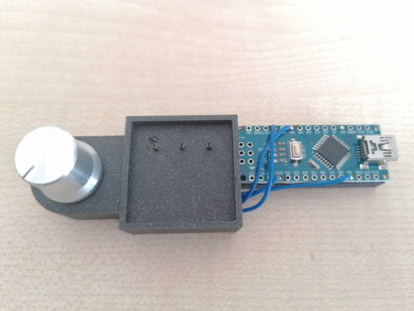
The Arduino is running the "Knob" example sketch (File -> Examples -> Servo -> Knob), which reads the value from the potentiometer and sets the corresponding position on the servo. The wires that need to connect to the servo go to "pogo pins" that stick through the square recess in the cradle. These are sharp spring-loaded contacts that press against the pips.
I was initially planning to try to sand back the clearcoat on the pips to expose the conductive contacts, but this turned out not to be necessary because the pogo pins are sharp enough to reach the brass through the lacquer, which leaves small scratches:
Evaluation
Uniformity
I rolled the die 200 times in each configuration to see how much bias the weight gives the die.
With the weight in the middle:
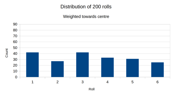
It's not exactly uniform here, but it's really not that bad.
There is a slight bias towards the 3 because the 3 is directly opposite 4, which the servo is mounted on, and the weight of the servo means the 4 ends up at the bottom slightly more often than it should. An easy-ish solution to this would be to put a counterweight on the back of the 3.
And there is a slight bias towards the 1, I think because the range on the servo is not quite enough to drive the weight far enough away from the 6. Probably this would be improved by making the die slightly smaller so that the range of the servo is a larger proportion of the size of the die.
And with the weight close to the 6:
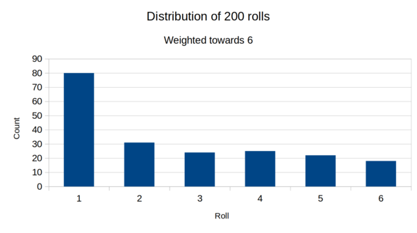
Moving the weight close to the 6 is certainly effective at making the die roll a 1. It rolls a 1 more than twice as often as any other number. It rolls a 1 about 40% of the time.
Subtlety
The biggest weakness is that if you shake the die, you can feel the weight inside rattling slightly. Anyone who has ever used a die before will immediately recognise that there is something going on inside, and at that point the jig is up.
The reason for the rattling is because the servo has some play in it.
Stavros suggested using springs to constrain the position of the weight. Alternatively I think you might get away with putting a strip inside on the 2 and/or 5 face, to press against the weight and stop it from rattling side-to-side. This would put more strain on the servo while moving the weight, but we don't care.
Practicality
To adjust the position of the weight, you need to hold the die on the cradle. But if you have the sleight of hand skills required to hold the die on the cradle without anyone noticing, then you might as well just carry 2 dice (one loaded and one not) and swap them as desired. There's really no need whatsoever for an adjustable loaded die. But I like the idea anyway.