
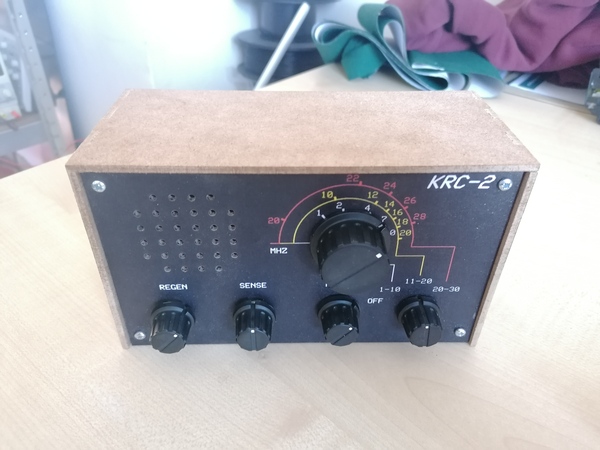
I recently learnt about regenerative radio receivers. They reintroduce some of the output of an amplifying transistor back into the input, to get more gain. It's a step up from crystal radios, and not as complex as superheterodynes. I bought a KRC-2 kit and this post is my review.
The short review is that I like it and if you want to build a regenerative receiver you should get it.
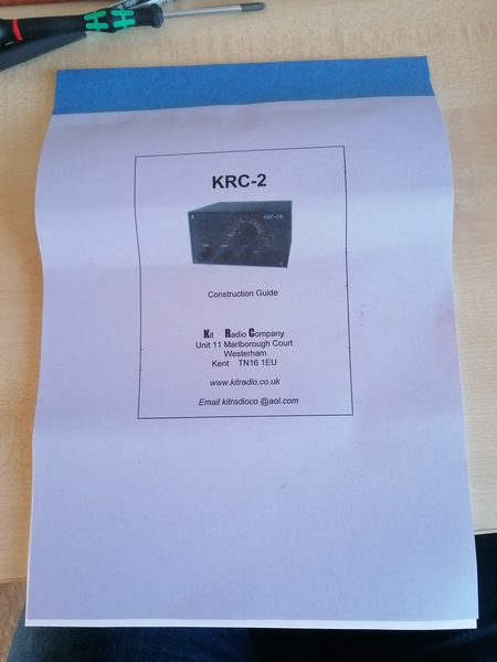
It took me about 3 hours to put the kit together. The instructions are pretty good and easy enough to follow, they come in a nice booklet.
Regeneration board
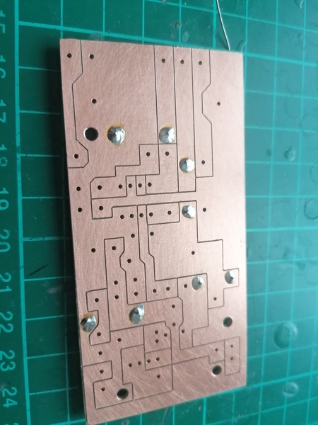
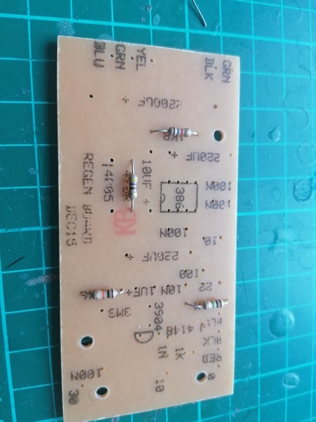
The first job is to solder up the "regenerative board". I was surprised to find that the copper side of the PCB is isolation-routed.
I have had a go at this myself in the past:
And while that particular PCB did work, it is the only success I've had. Every other attempt has failed in one way or another, because I was trying to design to the kind of tolerances I expect from JLCPCB.
I think the method used in the KRC-2 design is much better, because it maximises the width of the traces and the area for the solder pads. You are much more likely to produce a successful PCB with this method than if you try to lay it out like a normal PCB. I wonder how much trouble it is to make layouts like this in KiCad...
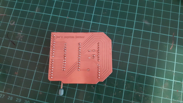
The other side seems to be screen-printed:
The footprint for the transistor requires the "base" leg to be bent the opposite way to what you'd normally expect, which confused me for a few minutes:
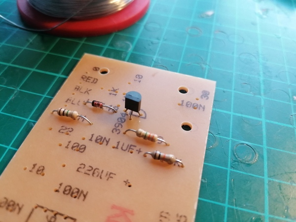
It's bent towards the flat side instead of the rounded side. This is contrary to both the usual practice and the diagram in the instructions:

The coil seems to be wound around a piece of plastic M10 threaded rod:
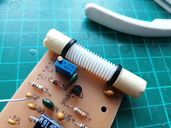
I think this is a good idea, as it gives you nice consistent spacing between the turns and means you don't need insulated wire.
Case assembly
With the PCB done, we move on to putting everything together in the case.
I was surprised to find a second PCB already fitted inside the case:
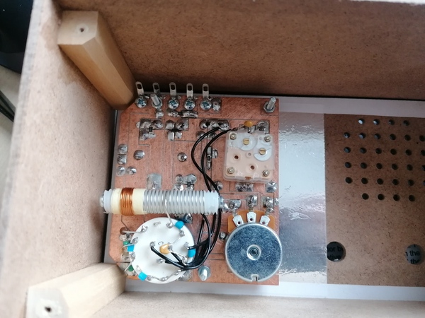
This is the "oscillator board". Why is this ready-made? Why not let me put this one together myself?
Probably because the soldering is much trickier (it uses SMD resistors, and has quite a few flying parts connected to the rotary switch) and by the looks of it the variable capacitor needs to be trimmed by hand, which presumably is quite a skilled job and can't be done until the board is assembled. Fair enough.
The KRC-2 seems to be an unusual regenerative receiver, in that it uses a 10.7 MHz oscillator mixed with the incoming signal from the antenna, which I haven't seen on any other designs. According to the documentation, this reduces spurious emissions and makes the regeneration control more stable. I don't know enough about radio to judge the pros and cons.
Assembling the case involves attaching the battery holders to the back panel, the "sense" and "regen" knobs and speaker to the front panel, and wiring the battery, antenna connection, regenerative board and oscillator board all together.
The speaker is glued to the back of the front panel with PVA glue around the edge of the paper cone. This would not be my first choice, although this particular speaker doesn't appear to have any provision for mounting hardware. Maybe you could hold the back of the speaker down with tabs against the metal? The glue seems to have stuck well enough, but I'm not sure whether it would rip the paper cone if I ever tried to take it apart.
The last step of the assembly is to solder wires on to the solder tabs at the top of the oscillator board. The instructions ask you to take the top panel off the case in order to access this, but I found this to be impossible. You can see here that the top panel is glued to the batten, which is also glued to the side panel:
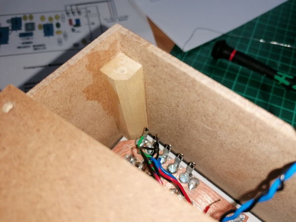
I'm not even sure how this is meant to have gone together. If the top panel were removable when the screws were removed, then it would either take the batten with it or not, and in either case there would be nothing remaining to join the side panel to the top panel. I wonder if this is a design revision that hasn't made it into the instructions?
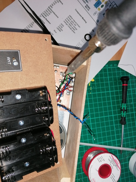
Anyway, unable to remove the top panel, I came up with an alternative method of soldering the wires to the tabs, which was to use some tweezer heroics to hold the wires in place and then reach the soldering iron all the way in to the corner:
This worked, but after I finished I had a better idea: I think if you were to remove both the front and rear panel, you could solder the wires in place on the bench at your leisure, and then snake one of the panels through the housing and screw them both back on from the outside.
Trimming
To trim the regeneration, there is a 20-turn trimpot on the regenerative board. The instructions ask you to set "sense" and "regen" to the middle, turn the trimpot all the way down, switch to "range 1" (which I assume is the 1-10 MHz range), give it 10 seconds to warm up, and then slowly advance the trimpot until a hiss is heard in the speaker.
Well I heard a hiss in the speaker even with the trimpot at minimum, and it hardly changed at all even when I turned it all the way to maximum.
I thought that probably I had made a soldering error, but before taking it all back apart I played around with it a bit and worked out that the quiet hiss I had been hearing in the speaker "doesn't count". The real hiss that you're looking for is much louder, and you're more likely to find it if you tune somewhere to the middle of the frequency range instead of at the very bottom.
Use
Moving left to right:
The "regen" knob is a potentiometer on the regenerative feedback, to control the strength of the regeneration. If you set it too low you don't hear anything (beyond the quiet hiss that is always present). Once you approach the critical point the hiss gets louder, and beyond the critical point it causes whistles and buzzes. You can tune it just beyond the critical point if you want to listen to Morse code or single-sideband, and just below the critical point if you want to listen to AM.
The "sense" knob is a potentiometer on the antenna input. It is suggested that you use this knob to control the audio volume, but it seems like the receiver would benefit from a second volume knob because attenuating the incoming signal does more than just make it quieter.
The next knob is labelled "fine" and is used to make fine adjustments to the frequency after having selected a frequency with the large knob.
The last knob is a rotary switch that selects between the 3 different frequency ranges, and is also a power switch.
The receiver is quite hard to tune, but that's fine, that's what makes it fun to use! If I just wanted to switch a radio on and listen to something I would have bought a mass-produced one.
It seems to be sensitive to how close my hand is to the left hand side of the box, which is where the coil on the regeneration board lives. In some configurations you can almost play it like a Theremin.
I expected to be able to tune some medium-wave stations at the bottom end of the 1-10 MHz range, but was almost entirely unsuccessful. I did manage to find TalkSport once, but it was extremely sensitive to small movements on all of the knobs. I've had most success listening to international stations between 10 MHz and 15 MHz. I don't know how much of this is due to my antenna (I have ~5 metres of wire hanging indoors, which is about 1/4 of a wavelength at 14MHz), how much is due to the receiver, and how much is due to ionospheric conditions. Sadly the foreign stations mostly seem to speak foreign languages, so I struggle to understand what they're saying.
I tried grounding the receiver through the electrical earth, but it seemed to introduce a lot of interference (choppy noises). For now I've got the "ground" connection tied to a metal shelving rack, which seems to be a slight improvement over nothing at all. I intend to replace the antenna with a wire hanging in the roof ridge in the loft, with a coax running down to my office. I don't know what to do about grounding, if anything. The KRC-2 instructions include a diagram that suggests hammering a spike into the ground.