
This post is a quick brain dump of the things I'm currently thinking about for Isoform. I think the time is almost right for the world to have F-Rep CAD.
At least, it started as a quick brain dump. It ended up so long that ChatGPT accused me of writing a manifesto. I won't mind if you skim it.
I've been surprised lately to find myself looking at objects in the real world and imagining the distance field around them. So beware, that might happen to you too if you get too deep into SDFs.
By the way, a good intro to the space of possibilities in CAD software is Leo McElroy's CAD in 1 hour,
Sketch workflow
I can make SDFs for 2d polygons and extrude/revolve them into 3d. The sketching tool is really lame, not parametric and no constraint solving. And needs to be able to support arcs and circles, and multiple separate shapes in a single sketch. But these problems are not too hard.
The starting point for implementing this is sdShape() from Inigo Quilez's 2d polycurve SDF, which provides support for both arcs and line segments.
Having made a 2d sketch, here are some things I want to do with it:
- extrude in a line perpendicular to the surface
- revolve around an axis parallel to the surface
- sweep along a path
- helical extrude
So far I have basic "extrude" and "revolve" implemented in Isoform. Sweeping along a path would have to come after I have a way to represent paths (probably a collection of non-closed sketch segments), but personally I don't use that operation very often in FreeCAD so I'm inclined to ignore it.
Extruding along a helix is really important for making things like screw threads. Basically only for making screw threads. But screw threads are really important.
Extruding along a helix is very close to extruding in a straight line and then applying a "Twist" operation to the extrusion ("Twist" is quite easy with SDFs, see Quilez's opTwist). It is not quite the same because that operation twists around an axis perpendicular to the cross section, whereas a helical extrusion goes around an axis parallel to the sketch. Also the "Twist" operation is one of those operations where "the maths just isn't that neat" and you end up with an SDF that breaks the distance property, which gets worse the further away the twisted object gets from a cylinder.
So I have more work to do on that. Helical extrusion is a firm requirement.
And then at the UI level, the sketcher obviously needs to do constraint solving. Currently the Isoform sketcher is just something Cursor wrote for me.
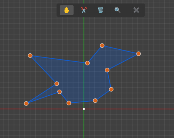
It lets you draw a single polygon, but it is completely imprecise because the vertices are just placed by hand with the mouse. Constraint solving in 2d sketches is a fundamental workflow for parametric CAD. I had kind of assumed that it would be easy to do as it's obviously a solved problem and the constraint solver doesn't need to care that I'm going to turn the sketch into an SDF, but reading Leo McElroy's introduction makes it sound quite hard. Possibly I would pull in a WASM wrapper of planegcs. Planegcs is apparently FreeCAD's constraint solver.
Or possibly I would do what I normally do which is decide that integrating other people's code is too hard and make a worse version myself from scratch.
User interface
Orthographic projection
For me, orthographic projection is mandatory for CAD. Orthographic projection has the important property that parallel lines in your object also appear parallel on the screen. Contrast this with perspective projection, where parallel lines converge to a vanishing point.
Doing ray marching with an orthographic projection is no harder than with the normal perspective projection, it just means all of the "rays" that you shoot out of the pixels on the viewport need to be parallel. And this has the maybe-unintuitive property that the object appears the same size on the screen regardless of how far away it is. So zooming in/out has to be done by scaling the size of the viewport, you can't do it by moving the camera back and forth because that has no effect.
For some reason, Cursor kept trying to rewrite my orthographic projection code to use perspective projection, I don't know why it thought perspective projection would be appropriate. Maybe it notices "SDFs" and "ray marching in a fragment shader", and it thinks it knows what to do. I added some text to .cursorrules to tell it that I really do want to keep my orthographic projection and it has left it alone since then.
Surface queries
A plain SDF gives you the distance to the surface from a point in space. (Or, without loss of generality, an F-Rep tells you whether a point in space is in or out of the solid object).
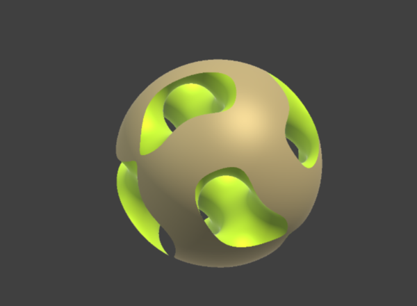
But we can do more than this. We can make our function yield a struct instead of a float, and then we can make it tell you more than one value. For example, we can make different parts of the object have a different colour. If our Sphere node writes a brown colour into the struct and our Gyroid node writes a yellow colour, and our Intersection node picks the colour of the surface whose distance it picked, then the Intersection of a Sphere and a Gyroid can look like this:
And with a smooth blend, we can blend both the distances and the colours:
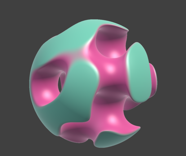
And if you care to, you can do the same thing for all (?) of the parameters for your Physically based rendering, to get more convincing surface effects.
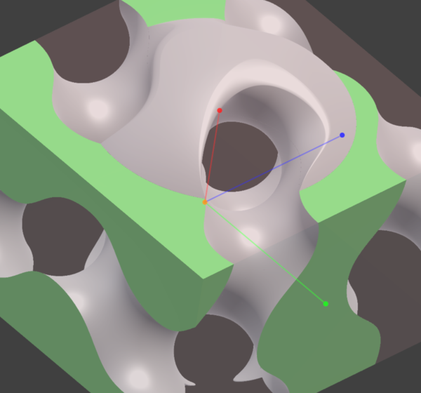
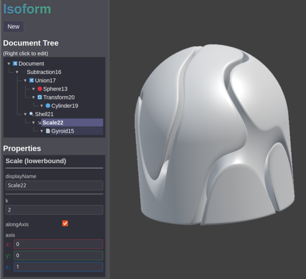
But we can also make the SDFs return a surface id. And then when a surface is selected in the user interface, we can pass the corresponding surface id into the shader to apply a highlight colour:

And we can do ray-marching in JavaScript, in the mousemove event, to detect the surface id that the mouse is hovering over, and have that highlighted in a different colour:
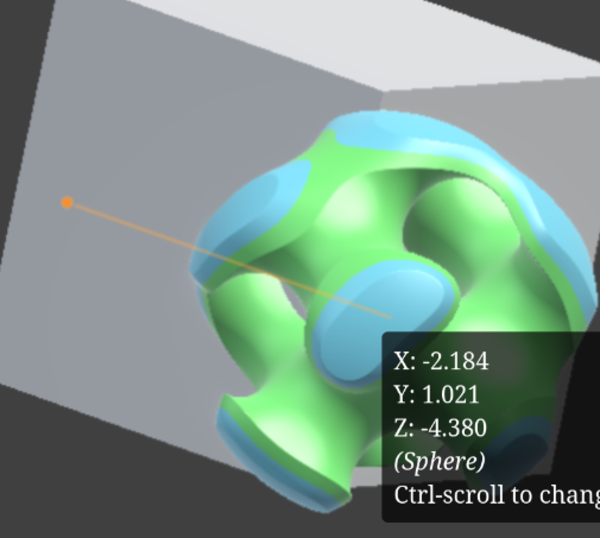
In that picture the Gyroid surface is selected (green) and the Sphere surface is hovered (blue). You can see that the surface changes halfway through the chamfer. (Arguably the chamfer region should count as a distinct surface).
Uniforms
To render the object on screen, we have to convert it not just to an abstract SDF, but to a fragment shader that can run on the GPU.
The naive way to do this would treat the object parameters as constants and recompile the shader every time you make a change. But a much better solution is to use uniforms to pass in the object parameters at runtime. Uniforms lie somewhere kind of in between variables and constants. A uniform is constant across every pixel on the screen, but can be changed in between frames.
For simple objects it can take maybe 100 ms to compile the shader and send it to the GPU, which doesn't seem too bad if you're editing the parameters with the keyboard, but it really kills the user experience when you allow editing with the mouse. Using uniforms is easy to do and means you can change object parameters for free, without even dropping any frames.
Blends
Fillets and chamfers are an important part of CAD. They're not a hard requirement. SolveSpace for instance does not support applying fillets and chamfers other than modelling them by hand. But for me that makes it hard to justify using SolveSpace. Fillets and chamfers are about as hard a requirement as you can get without actually being a hard requirement.
In FreeCAD filleting and chamfering are 2 different tools, but in SDFs we don't really draw much of a distinction between the two. So for now I'm referring to fillets/chamfers generically as "blends". And in Isoform the "chamfer" parameter is actually a float. chamfer=0.0 means you get a fillet, chamfer=1.0 means you get a chamfer, and in between is a linear interpolation of a fillet and a chamfer. I don't know if this will end up being useful, but it was easy to do.
Fillets on boolean operations are easy to do with any of Quilez's smooth min functions. I didn't figure out the maths for chamfers myself, but I stumbled across this shadertoy by "TinyTexel" which contains a decent implementation of a "chamfer min". It is actually smooth even at the interface between the surface and the chamfer, but that is a benefit because it means the first derivative of the surface has no discontinuities (which means surface normals calculated by automatic differentiation work properly). And you can tune how sharp the transition is.
But sometimes you don't want to have to structure your CSG tree according to the blends you want to apply. Sometimes you just want to model your part, and then later on notice that you want a fillet where 2 surfaces meet. Wouldn't it be cool if you could somehow click on the edge and just ask for a fillet on that edge?
Yeah, it would. I wish I could do that. That is how it works in FreeCAD, and as long as the intersecting surfaces are not too weird it usually doesn't segfault.
I have done some work towards supporting this kind of flow in Isoform. Using "Surface queries" we can easily let the user select a surface by clicking on the object. Selecting edges to fillet by selecting the 2 interacting surfaces is good enough for me.
But how do you actually apply the fillet?
For example take the tree Union(Intersection(a,b), c) where a,b,c are 3 surfaces in the part. If you want to fillet (a,b) then that's easy, you can apply the blend at the Intersection. If you want to fillet (a,c) then you have a problem. If you apply the blend at the Union then you'll fillet (b,c) as well, which does not reflect the design intent.
So my first idea was instead of having fixed blend parameters at each boolean operation, we could look up the blend parameters at runtime based on the surface ids of the children. I thought this was obviously going to work, and I implemented it, and...
The distance field looks like this:
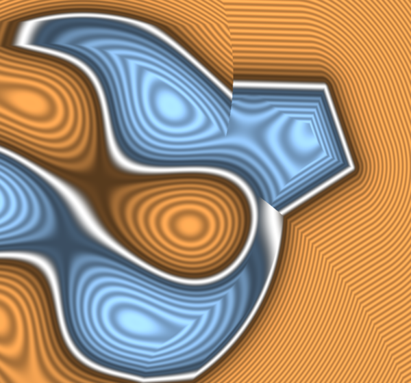
(Blue is negative, orange is positive, white is 0, ripples represent isolines).
There are discontinuities in the distance field where the blend parameters change! Disaster.
So that was my first clue that this might be quite a thorny problem.
A second idea is that we could have the expression tree propagate up the distance to the nearest surface that got rejected by a min/max function, and fade out the blend as we approach that surface. That kind of works:
Here there is a chamfer between the Sphere and the Gyroid, but not between the Box and the Gyroid, and you can see that the chamfer tapers off to 0 as it approaches the surface of the Box.
So that algorithm happens to work for that specific case, but it doesn't work very well at all in some other cases. In my opinion it does not capture the design intent very well. Having your fillets randomly fade out just because they go near something else is not the way. And it becomes impossible to fillet a corner where 3 surfaces meet.
So the third idea is to rewrite the tree so that blended surfaces do appear as siblings and you can apply the correct blend. This is possible because (thank the Gods) min(a,b) and max(a,b) both distribute over each other.
Which means for example you can rewrite min(max(a,b), c) as max(min(a,c), min(b,c)) without changing the meaning! That means it is possible to rewrite the tree to make the arguments of any arbitrary blend into siblings of each other, and then you can apply the blend at the relevant min/max.
But, ah... it doesn't end there sadly. What if you want some blend between (a,c) and another, different, blend between (a,b)? You could rewrite the tree back to how it was before to handle the (a,b) blend, but then you can't do (a,c) any more. So keep applying the distributivity rewrite:
min(max(a,b), c) => max(min(a,c), min(b,c)) => min(max(a, min(b,c)), max(c, min(b,c))) => max(min(min(a,b), min(a,c)), min(c,b), min(c,c))
(I wrote the line above by hand, it could have errors, it is meant to be repeated application of the same rule. I tried getting ChatGPT to check if I did it right, it was convinced I made a mistake but it eventually gave up and said "I hate this, but I can't break it". I am pretty confident the rule holds even if I made an error in applying it.)
And there. Now we can apply one blend to min(a,b) and another to min(c,b).
However, I still don't know if it ends there! OK, we now have leaf nodes that are blended correctly, but do we need to apply blends at the higher level min/max that join them together? Or does it all work itself out? I don't know.
And I won't find out for a little while because I still haven't successfully stumbled across the correct algorithm for deciding where to apply the distributivity rewriting rule. But resolving the tree rewriting algorithm is my current focus, I hope to get it working this week. Btw if you know the correct algorithm please email it to me, thanks.
Tools
Volume, mass, centre of mass
There is a neat way to calculate volume, mass, and centre of mass, if you can take integrals.
For your distance function f(p), define g(p) = f(p) < 0 ? 1 : 0, but with a smooth approximation of the ternary operator (e.g. smoothstep instead of step, with whatever sharpness you think is appropriate for your desired precision level).
Integrate g(p) over all space (e.g. over your bounding box). The result of the integral is the volume of your object in O(1)!
If the object is all one material then you get mass by multiplying by density. If it has multiple materials, then propagate them up your expression tree the same way as you handle colours and surface ids, and then h(p) = f(p).dist < 0 ? : f(p).density : 0.
Integrate h(p) to find mass.
And you can binary search within your bounding box, for each axis in turn, to find the point that has 50% of the mass on either side. That point is the centre of mass, found in O(lg N) where N is the level of precision you want (e.g. to find the centre of mass in each axis to 1 millionth (N=106) of the bounding box side length would take 20 steps).
But... this is another place where the maths "just isn't that neat". Automatic integration isn't nearly as straightforward as automatic differentiation. So I think we'd need to use a numerical method to compute the integral. It would look nearly the same as I described above, except multiply everything by O(N^3).
But I think Mathematica can compute integrals analytically, so it is probably possible.
Surface texturing
Surface texturing is something I'm really excited about. We can permute the distance field according to any arbitrary function we define.
Currently I have surface texturing with a "Distance Deform" operator:
That adds a "random" texture to the surface, by multiplying together a bunch of random trigonometric functions applied to the point in space and adding the result to the child distance field.
But instead of just adding random texture, or other procedural textures, we could load an image file and send it to the GPU as a 2d texture, and then extrude it along (say) the Z axis, and tile infinitely in X and Y, scale it etc., and then deform the distance field according to the (interpolated) value of the image.
As an example you could make a 2d SDF of a "checkerplate" texture and have it apply to parts of your model as distance deformations. Adding massively-repeating fine-detail textures in this way is something that is easy with F-Reps but really hard with B-Reps.
It could also be a really neat way to apply logos to surfaces for example. It would make the surface of the model "bulge out" where the logo is. And maybe you could have another mode where the image is revolved, or extruded radially instead of linearly, and pick whichever one best fits the surface you're trying to map it on to.
(Btw would a radial extrude be a useful thing to do with sketches too? Maybe).
CAM
CAM isn't really something I'm bothered about for Isoform. I'm really mainly interested in 3d printing.
Worst case, I can export a mesh and do CAM on the STL file with Meshmill, or something else.
The only reason I'm thinking about CAM is because something really cool is possible with SDFs.
So we know that the SDF gives us the distance from a point in space to the nearest point on the surface. That means you can put a sphere at that point in space and know that it won't penetrate the surface. And if you then march your "ray" forwards by the radius of the sphere, you test a new point on the perimeter of the sphere, and you get another sphere, and so on, until you hit the surface and get a sphere of 0 radius. And that's how we do "sphere tracing" for SDF rendering.
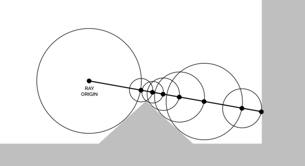
(From Wikipedia)
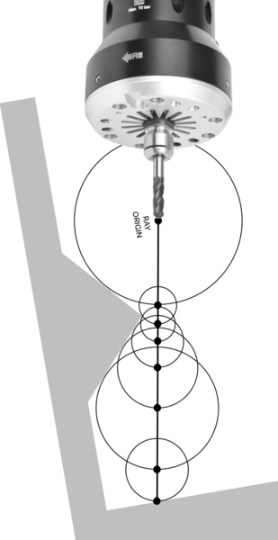
There are 2 core problems in 3-axis CAM. The first is working out what path to follow in XY, and the second is how deep to plunge it in Z at each point on that path. And with SDFs we have a really neat way to work out how deep we can plunge a ball-nose tool.
Rotate the ray-marching problem in your mind slightly, and imagine shooting rays vertically down from a CNC spindle. Stop when the distance to the surface equals the radius of your tool. Now you've found exactly how far you can plunge a ball-nose end mill without intersecting the geometry! And you've done it in, let's say from my experience, 10 or 20 evaluations of the SDF, regardless of the size of your tool, and with arbitrary precision.
Compare that to how Meshmill works, where we find out how deep the tool can plunge by testing against a neighbourhood of pixels in a heightmap. The area of the neighbourhood is quadratic in both the radius of the tool and the resolution of the heightmap. So it gets expensive really fast if you want high-resolution heightmaps and large tools.
So sphere tracing could be a good way to do CAM with SDFs... but only for ball-nose tools! I haven't yet worked out a good way to work out how deep you can plunge a flat end mill, which I would consider to be a hard requirement for CAM. Ball-nose tools are cool, but it's not very often you make stuff only with ball-nose tools.
Meshes
Export
Exporting meshes is critical because if you can't export meshes then you can't 3d print your models, I claim but do not prove.
(I don't claim that. Obviously you can slice from an SDF, but you'd need to make a custom slicer. Do you want to make a custom slicer? I don't. So for now, meshes).
Turning an SDF into a triangle mesh is relatively straightforward with marching cubes. This is a relatively simple algorithm, but requires some enormous lookup tables. Cursor wrote pretty much the correct algorithm on the first try, and it made what I would call a bloody good effort at typing out the lookup tables off the top of its head. It didn't get the lookup tables quite right, which meant my first few attempts at meshing had holes in them:
But it didn't take a lot to get it to work:
I would definitely credit Cursor with having done the majority of the thinking on the Isoform mesher. (So far).
Currently it evaluates the SDF at every point in the voxel grid, and then uses marching cubes to make a mesh and writes it out as an STL file.
The next big improvement here would be to use interval arithmetic to rapidly classify large regions of space as either inside or outside the volume, without having to evaluate every single voxel within the interval. You should see Matt Keeter's talk on Implicit Surfaces & Independent Research for more info on this, or his paper Massively Parallel Rendering of Complex Closed-Form Implicit Surfaces.
I already have a way in Isoform to compile an SDF to a version that works with interval arithmetic, so it shouldn't be crazy hard to make the mesh export more efficient. But it's not a focus for the time being because fundamentally the "core technology problem" is solved, and I don't need to create meshes very often.
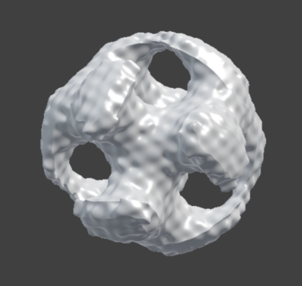
One good milestone was 3d printing the first Isoform-modelled part:
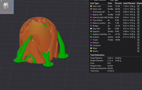
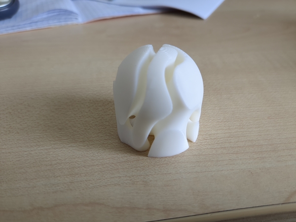
It is a kind of weird and non-useful shape, but it was chosen because it is easy to do with SDFs and hard to do with B-reps. The Shell of a Gyroid separates space into 2 disconnected halves, so this is kind of a print-in-place fidget toy with 2 components that can't be separated. Lucy calls it a coral reef.
Import
Importing meshes is much less critical. Importing meshes allows you to "remix" other people's models. I almost never do this, because working with imported meshes in FreeCAD is way too compute-intensive.
It is relatively straightforward to make an SDF from a triangle mesh, there is Isoform code for this in js/nodes/mesh.js. You need to calculate the distance to the closest point on the closest triangle of the mesh, which is the same as the min() of all the distances to all the points on all the triangles!
So, yeah, obviously this is way too compute-intensive to be running in real-time on large meshes.
So the next thing is instead of just sticking the giant mesh SDF in the document tree, we can sample the mesh SDF in a 3d grid, and store the distance values from the 3d grid in a 3d texture, pass the 3d texture to the GPU, and then sample the 3d texture in the fragment shader. And then we get a kind of quantised version of distances to the triangle mesh, but with O(1) lookup.
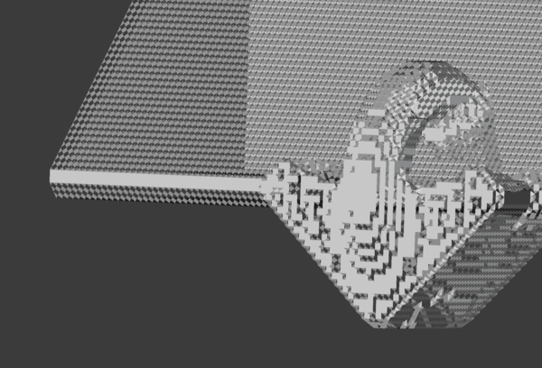
The good news is that linear interpolation of distances to flat planes still results in flat planes! The bad news is that linear interpolation of distances to sharp edges does... not result in sharp edges:
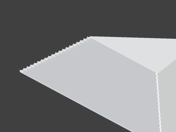
So maybe the best thing to do is increase the grid resolution. That would make the initial import of a mesh slower (in proportion to the number of points in the grid), but wouldn't affect runtime performance until the grid gets too big for GPU memory.
I was quite disappointed that the sharp edges become stair-stepped. Valve published a paper Improved Alpha-Tested Magnification for Vector Textures and Special Effects in 2007 on the use of SDFs sampled in 2d which seems to show smooth-ish reconstruction of straight lines (figure 1b).
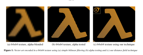
And this does generalise to 3d as smooth reconstruction of flat surfaces, but I don't know if there's a good way to modify it to get smoother reconstruction of straight lines.
(I'm not using "their technique" from figure 1c because it is complicated and weird and the paper doesn't really explain how to do it. But maybe it would help.)
For now the best I can do is crank up the resolution of the 3d grid, and use the interval arithmetic recursive subdivision method to reduce the amount of mesh SDF evaluations I need to do.
Mathematics
SDF arithmetic in Isoform is handled by a library that I'm calling "Peptide". It's a "library" in the sense that it is conceptually self-contained. It currently lives inside the Isoform git repo. It allows you to write code like:
let y = P.add(P.const(12), P.var('x'));Which is an admittedly really awful syntax for saying y = 12+x.
But here y is not a number. y is a Peptide expression, and with a Peptide expression we can:
- straightforwardly evaluate in JavaScript
- compile to JavaScript source code (and then eval() the JS code, which is faster than direct evaluation if you want to do it lots of times)
- compile to GLSL shader code
- or do any of the above but for interval arithmetic
- or take its first derivative, as another Peptide expression, with automatic differentiation
With Peptide, I get to write a single implementation of each node in my SDF tree, and I get to use it in JavaScript, and in fragment shaders, and I get to use interval arithmetic in any of those places, and I also get automatic differentiation.
I found Cursor was really good at writing the automatic differentiation code.
Peptide is basically a rip off of Matt Keeter's Fidget, but with a feature set that better suits what I want. Joe Hewett once said that I "don't know how to use other people's code". He might have been right.
Rendering
Interval arithmetic
I was hoping to be able to use interval arithmetic to do "binary search ray marching". We would arrange for the viewport to be perpendicular to some axis (say Z), and in the fragment shader, evaluate an "interval ray" which has a 0-sized interval for X and Y, but spans the entire bounding box in Z. Evaluate the SDF over this interval. If the resulting distance interval doesn't contain 0 then you know the ray can't hit the object.
That much works.
Then the plan is if the ray does hit the object, then cut the interval in half, and evaluate the ray that goes halfway into the scene. If that hits the object, then come halfway to that one, otherwise do halfway from there to the end, and so on.
The reason it doesn't work is because interval arithmetic is giving conservative bounds on the values in the interval. It is true that if the distance interval doesn't contain 0 then the ray doesn't hit the surface, but it is not true that if the distance interval contains 0 then it does hit the surface.
So I don't think binary search ray marching works, and we're stuck with sphere tracing.
Sphere tracing artifacts
Sphere tracing is a really good way to rapidly march a ray towards a surface perpendicular to the ray, but it has a pathological case when marching a ray near a surface that is almost parallel to the ray.
At each step, the ray is not very far from the surface, so it can't advance very far into the world. But since it is almost parallel to the surface, it isn't getting much closer, so the same thing happens again at the next step.
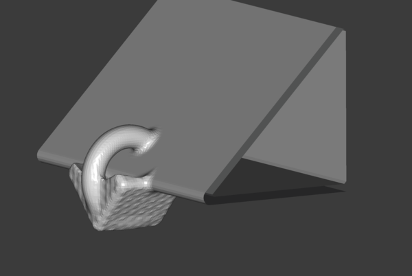
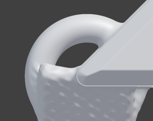
If the parallel surface is long enough then you might hit your step limit without reaching the surface. My first implementation said that in this case the ray had not hit the object. Consider this object:
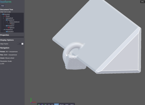
If the long flat side of the triangular prism is perpendicular to the screen, then it is parallel to the rays, and if you zoom in you get holes in the model:

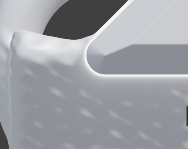
An improvement (in this case) is to say that if the ray didn't hit the object then we'll pretend it did if the distance to the object is small:
This gives a less jarring visual artifact, but is still bad.
My final improvement is to blend in some "fog" based on how many steps of ray marching it did.
This gives the appearance of some kind of bright reflection near the edge of flat surfaces. The natural human reaction is to rotate the object to get rid of the bright reflection, which then allows the ray to converge quickly and you can see what you're doing.
Conclusion
Well that's basically all of the ideas I have for how to make an F-Rep CAD program. Please steal anything you find useful. And please get in touch if you are working on F-Rep CAD software, I don't think there are all that many of us.
And thanks to:
Inigo Quilez for the world's greatest reference library for SDF information.
Kevin Lynagh for sending me lots of great information, he wrote CADtron, and introduced me to Matt Keeter's work.
Matt Keeter for the talk and paper about applying interval arithmetic to SDFs, and for Fidget.