
I've been a happy FreeCAD user for about 5 years. Occasionally I read comments on Hacker News from people who are raving about SolveSpace. I have briefly looked at SolveSpace before and didn't really get it. It seemed so obviously inferior as not to be worth looking at. I assumed that all the SolveSpace users were just not willing to put in the work to understand FreeCAD, and they only thought SolveSpace was good because they didn't know how good FreeCAD is. But it occurred to me that I was doing exactly the same thing to SolveSpace: I assumed it was worse than FreeCAD mainly because I couldn't be bothered to put in the work to understand it. So this evening I finally gave it a proper try and noted down my observations.
Obviously, 5 years of experience in FreeCAD compared to about 3 hours in SolveSpace is not a fair comparison. Also: I love FreeCAD. Like... a lot (call it Stockholm Syndrome if you want). Please bear that bias in mind while reading. I also think 3 hours is just enough time to run into loads of things that I can't do in SolveSpace, but not enough time to discover great new things that I couldn't do in FreeCAD. Most of this post is from the perspective of "what's different in SolveSpace compared to FreeCAD?". If you're a happy SolveSpace user and you think I got something wrong, please correct me!
Whether you're using FreeCAD or SolveSpace, you should definitely run an up-to-date version. The version available in apt is very out of date in both cases. For FreeCAD I recommend the latest weekly build AppImage (not the latest stable on the website, that one is also woefully out of date). For SolveSpace I recommend the solvespace snap package.
Overall workflow
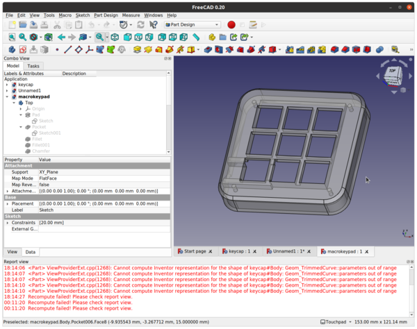
I mostly use the "Part Design" workflow in FreeCAD (distinct from "Part", just to make things easy to understand). The workflow in SolveSpace is almost exactly the same as Part Design, so I found it very easy to get started, after watching a 9-minute video of operating the user interface. Most of it drops straight into slots in my brain that already exist for Part Design.
The black background colour for the UI in SolveSpace is an unusual choice.
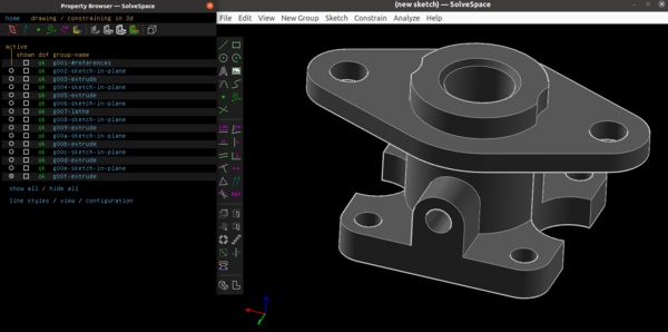
It makes the software feel much more foreign and confusing than it really is. But it also contributes to the general "feel" of the program. You feel like you're working more closely with the geometry of the part than you do in FreeCAD. So I don't know if the weird colour scheme is a good thing or a bad thing overall.
What's better in SolveSpace?
The SolveSpace workflow is more cohesive in a way that is hard to give a feel for if you don't actually try it out.
In FreeCAD you have one view for creating a sketch, and then when you're done with the sketch you close it and you have a separate view for turning the 2D sketch into a 3D feature. In SolveSpace it's all the same view. In particular this means that defining things like the length of an extrusion or the angle of a revolution are done using exactly the same constraint solver as the sketch uses! This was a revelation to me.
In FreeCAD you have this amazing constraint solver available in 2D for your sketches, but then when you want to turn them 3D, it all disappears and you have to choose between a simple length, or a pad up to an existing face, or a pad up to an existing face with a custom offset, and so on. The available options are quite extensive, but not exhaustive, and are wholly unnecessary in SolveSpace. In SolveSpace, the extrusion is just dimensioned using constraints. You can very easily do complicated things to decide the length of an extrusion without doing any maths in your head. Just define construction lines in 3D space and constrain the extrusion to meet your construction lines. Easy peasy. This is very powerful and I wish FreeCAD worked this way.
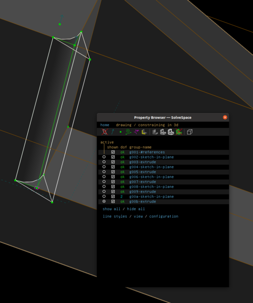
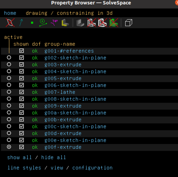
I also like that the SolveSpace "shown" checkbox can make many "groups" visible at the same time. A "group" in SolveSpace is roughly the same as any single item in the project tree in FreeCAD. If you turn several of them on at once (the default behaviour is to show them all at all times) then you get to see all of the elements in every sketch at once (but you only see the constraints of the active group):
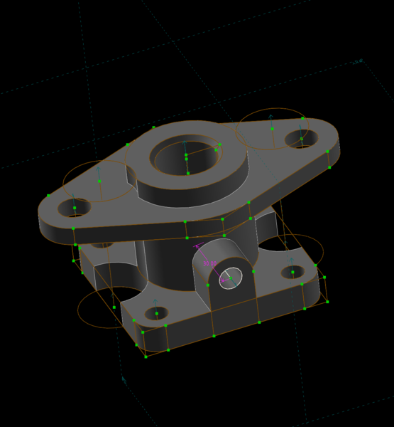
In particular, these can then be used to reference other geometry to, to create new sketches, and so on. There's no need to create datum planes or datum lines like you do in FreeCAD. You can just create construction lines directly in 3D space, referencing any geometry in any "group". I think this is a big part of what makes SolveSpace fun to use.
What's worse in SolveSpace?
Fillet/chamfer
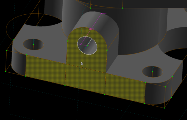
There are no fillet/chamfer tools in SolveSpace. This was a big disappointment. The best way to create a fillet or chamfer is to model it in the 2D sketch. This obviously doesn't work for the edges of the flat faces created by the extrusion. In those cases you need to create a new sketch and cut it away from the edges of the extrusion. You also need to make sure that the edges of your sketch do not exactly line up with the edges of the existing part, otherwise SolveSpace gets confused and forgets to fill in some of the adjacent faces, which leaves holes in your part:
The solution is to space the bounds of the fillet away from the existing part geometry:
This whole method is annoying and time-consuming and will result in SolveSpace-modelled parts having sharper edges than FreeCAD-modelled parts with almost 100% probability, because softening the edges is too much trouble.
I'm not saying FreeCAD fillets and chamfers are bug-free! Far from it. Few among us is the FreeCAD user who has not lost an hour's work when the fillet segfaulted an unsaved project. But with time you do learn what kinds of things are likely to crash the filleting tool, and mainly you learn to save before applying risky fillets.
Thickness
I don't use the Part Design Thickness operation very often, but when I do it is a big time-saver. It allows you to model things like an electronics project enclosure as just the outer shape, and then turn it into a hollow part with uniform thickness and 1 open face with a single click. In SolveSpace I think you'd have to manually model both the external and internal geometry, I'm not aware of any way to automatically create the uniformly-sized offset.
Rotation
I can't figure out how the 3D rotation works in SolveSpace. There are 2 options (the default one and "turntable") and they are both equally baffling to me. They both have the peculiar property that you can drag the mouse around in a circle while rotating, and when the mouse gets back to the start point on the screen, the part will not have returned to the starting orientation. I expect this is the sort of thing that you get used to with time, but for now rotating the part is very much a guessing game for me. It doesn't work like any 3D mouse rotation I am familiar with.
Pad direction
Normally when you create a Sketch and make a Pad (in FreeCAD) or a Union extrusion (in SolveSpace), it comes "up" out of the sketch, and towards the direction you were looking at it from, and when you make a Pocket (FreeCAD) or Difference extrusion (SolveSpace) it goes in the other direction. All very good and sensible.
In FreeCAD if you want your Pad or Pocket to go in the other direction, you tick the box that says "Reversed" when creating the pad.
In SolveSpace if you want your Union or Difference extrusion to go in the other direction, you need to delete the extrusion, delete the sketch, and start again with a workplane that faces in the other direction. I hope I'm wrong on this one, because it seems unlikely that there is deliberately no way to reverse the direction of an extrusion.
Update: u/henrebotha points out that you can reverse an extrusion just by clicking on the surface and dragging it in the opposite direction. This is great! It's actually quite intuitive, I don't know why I didn't think to try it. I must have still been stuck in the FreeCAD mindset of trying to interact with the GUI rather than the part.
Sketches
What's better in SolveSpace?
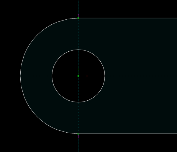
SolveSpace visually shades the enclosed area of the sketch so that you can see which parts are "positive" and which parts are "negative". This is good and FreeCAD should copy it.
(It's a dark blue-ish colour on a black background; for some reason it's easier to see in the application than in the screenshot)
SolveSpace also helpfully points out where your sketch is non-closed so that you have half a chance of fixing it.
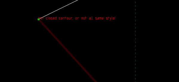
It's very annoying to
spend a long time on a complicated FreeCAD sketch, and then go to create a Pad, only to find that it can't create
the Pad because the sketch is not a closed shape. You then have to manually check every vertex in the sketch to find out which ones
aren't connected properly, only to find that 2 points that looked the same are actually 0.01mm apart.
Update: u/strange_bike_guy points out that FreeCAD has a "validate sketch" tool that can automatically find missing coincidences within a given tolerance.
Once you've created a sketch in 3D, I love that you can click and drag the unconstrained face and move it around in 3D space. I grant that this is usually not particularly useful, because you'll usually want to add a constraint to the length anyway, but it adds to SolveSpace's feeling of a direct connection to the part geometry. In FreeCAD you just have a text box to type a length into and absolutely no chance of manually dragging the extrusion around.
In FreeCAD if you want a sketch to reference some geometry that already exists on the part, you need to use the "external geometry" tool to bring it into the sketch. This never really occurred to me as an unusual thing to have to do, but in SolveSpace that tool just... doesn't exist. You just don't have to do it. All of the geometry is already available to use, you don't have to do anything weird to bring it in. This just seems obviously better. I'm not sure why FreeCAD isn't this way.
What's worse in SolveSpace?
Sketch attachment
In FreeCAD you can create a sketch on any existing flat face of the part very easily. Just select the face and then click the "create sketch" button. In SolveSpace, even though flat faces are highlighted in a weird yellow mesh when you hover over them, selecting a face and then trying to create a "workplane" based on it does not work.
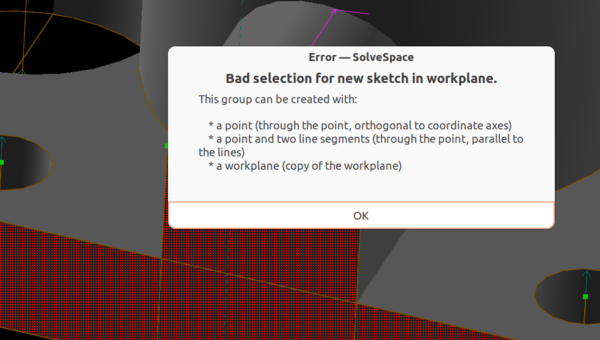
Even though if you select a single point, creating a workplane based on the point works fine. Doesn't a face describe a plane better than a point does? I don't really understand the thinking there. What you have to do instead is select 2 of the lines that form the edges of the face, then a point somewhere on the face, and then create the workplane. It works fine but feels over-complicated in the common case of creating a sketch coplanar with an existing face. I also don't see what the point adds over the 2 lines. Don't 2 coplanar lines describe a plane on their own? It's also difficult to make a workplane on a circular face, because you don't have any straight lines to use.
In FreeCAD once you've created a sketch on a face, you still have the option to adjust the attachment position of the sketch so that it is offset from the face you attached it to. I don't do this particularly frequently, but when I do it is a big time-saver compared to setting up a datum plane.
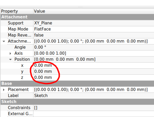
In SolveSpace, you have to manually set up some construction geometry that is offset from the face and then create your workplane on your construction geometry. It works, and it's not that much more work than just creating a workplane off existing geometry. But what is much worse in SolveSpace is that once you've created the workplane, if you didn't have the foresight to add an offset in the first place, you can't add an offset at all. If you change your mind about where you want the sketch, you need to delete it and start all over again. (And, actually, I'm not sure how this works if you change your mind about where you want a sketch that is several steps back in the Property Browser; do you need to remake everything that came later? I hope not. Probably someone who knows more about SolveSpace than me would know a way to adjust a sketch attachment without breaking everything that came later).
Multiple constraints
In FreeCAD you can select any number of lines and set an equality constraint on their lengths. Or you can select any number of points and put a vertical constraint on them to make them all lie in a vertical line. In SolveSpace, these constraints can only operate on 2 lines or 2 points respectively. This means when you have a lot of lines to make equal, or a lot of points to make vertical, it takes twice as many clicks in SolveSpace as it does in FreeCAD.
Redundant constraints
In FreeCAD there is an option for "auto remove redundants".
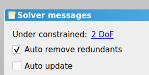
This allows you, for example, to set points coincident with each other, and if the points already have some constraint that meant they were already coincident in one axis, that constraint can be automatically removed from one of the points to avoid over-constraining the sketch. SolveSpace doesn't appear to have any workaround for this. The closest thing it has is "ignore redundant constraints", but see the "Bugs" section below for why this isn't satisfactory. The best way to avoid this is to try to remember to constrain points to lines rather than to other points. And when you know you're going to make 2 circles symmetrical about the origin, for example, remember to place one circle on the X axis, and remember not to place the other circle on the X axis, otherwise after you add a symmetry constraint across the Y axis, you'll have 2 separate constraints putting the circles on the X axis, which makes the sketch over-constrained. Just a bit more forethought required in SolveSpace than in FreeCAD.
Unconstrained elements
In FreeCAD, unconstrained elements in sketches are shown in a different colour to constrained elements (white instead of light green).
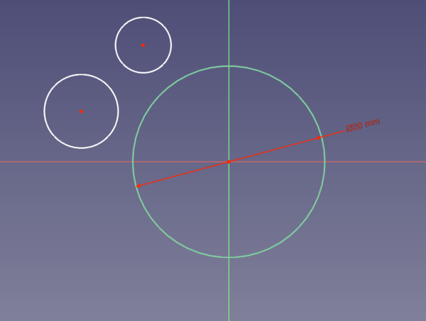
This makes it relatively easy to locate the unconstrained parts. SolveSpace doesn't have any obvious way to point you towards the unconstrained elements, you just have to think about it and find them on your own.
Symmetry across a point
SolveSpace can't do a symmetry constraint across a point. It can only make 2 points symmetrical across a line. Making 2 points symmetrical across a point is the fastest way to centre a rectangle on the origin, and maybe 50% of my parts in FreeCAD start this way. In SolveSpace you'd have to make the top edge symmetrical across the Y axis, and the left edge symmetrical across the X axis. (And then you'd have to manually remove the vertical and horizontal constraints on the rectangle, else it's over-constrainted). It just takes more clicks in SolveSpace.
Cross-section view
In FreeCAD's Sketcher workbench there is a button called "View Section" that turns the view into a cross-section of the part along the sketch plane.
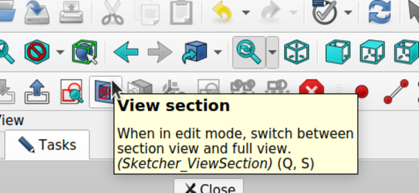
That means every feature on the part that would sit between the "camera" and the sketch plane is hidden, so that the sketch is unobscured. This is a very useful feature. I couldn't find anything equivalent in SolveSpace, which means if you work on a sketch that intersects the existing solid, you're going to struggle. The closest thing I could find was "draw occluded lines" so that you can see the lines on your sketch even though they're not on top. But this can presumably get very cluttered in a complicated part.
Assembly
FreeCAD has a lot of different assembly-related workbenches. I don't use any of them. I think there are too many options and they all work too differently, and there is a sort of paradox of choice where I can't work out what I should be using, and I work around it by manually positioning and rotating separate bodies using the property editor instead.
SolveSpace seems to have a simple assembly system built-in. I have not used it yet, but it seems so much simpler that if I do use SolveSpace for a non-trivial project then I will almost certainly use the assembly system.
CAM
CAM seems to be missing from SolveSpace. I expect even if you really liked SolveSpace and hated FreeCAD, the best way to do CAM would be to model your part in SolveSpace, and then load it in FreeCAD to use the Path workbench. (Unless you want to do 3D CAM, in which case you should definitely try Meshmill instead!).
There are some CAM-related options in the "configuration" window (window? tab? zone?), namely "cutter radius offset" and "exported g code parameters" but I couldn't find anything in the user interface that would actually generate any G-code. I'm not sure if it is not implemented yet or just too hard for me to find. But I didn't look very hard, and besides, even if it is there, the fact that "cutter radius offset" is a global option does not suggest very advanced toolpath generation.
Bugs
FreeCAD bugs
FreeCAD has plenty of bugs of its own. In FreeCAD, bugs frequently segfault the application. If you try to do anything complicated in FreeCAD, it is going to segfault on you. That's just part of the experience. Remember to save frequently. When it segfaults, just reload FreeCAD and try the same thing again. Most of the time it will work. If you have found something that reliably segfaults FreeCAD then you just need to find a different way to do what you're trying to do. But segfaults are just part of life when you use FreeCAD. The first time it happens it feels like a complete impediment to getting any work done, but eventually you realise it's just a low percentage drain on productivity and not a big deal. I'd rather have a Russian Roulette filleting tool than no filleting tool at all! And I would definitely say stability improves with each new release I download.
FreeCAD has an automatic project recovery tool that is meant to restore your unsaved work after a crash. I'm pretty sure it doesn't work. It's some sort of complicated cruel joke. The only time it ever restores what you were working on to the state you wanted is when it was a test part that you didn't need. But it doesn't matter. Just learn to save your work!
I didn't have a single segfault from SolveSpace, which is good. In fact I didn't find any bugs that would trash your work without warning.
Property Browser window going all black
I found that the Property Browser window sometimes goes completely black and I need to waggle the mouse over it to get it to redraw. I don't know why.

Unwanted open faces
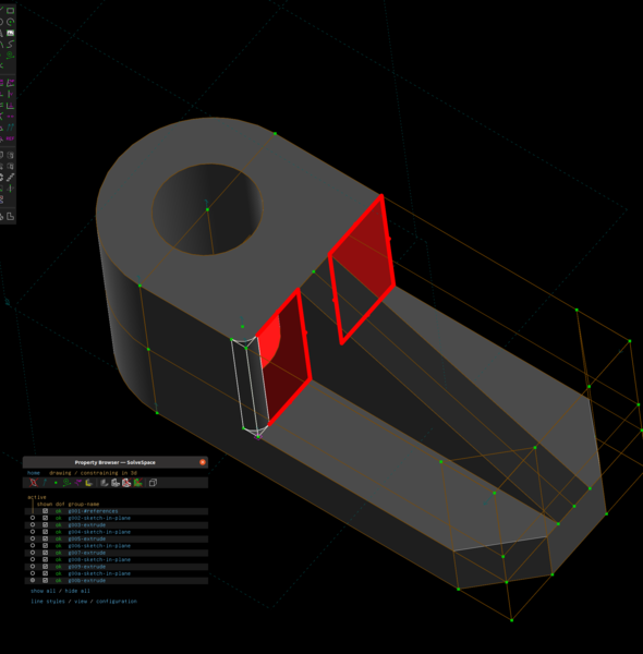
I consider the thing where it makes open faces if you try to make a fillet that is exactly coincident with existing geometry to be a bug. But let's say you don't! Let's say you want open faces when you try to make a fillet coincident with existing geometry. Even then, surely this is a bug:
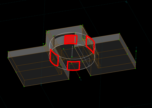
I tried to create a cylinder that partly passed through open space and partly joined to an existing solid, and it just didn't work at all. It left some open faces for no reason that I can discern. I have come across this sort of thing in FreeCAD, but only a handful of times ever, and always when doing something very weird. In SolveSpace it seems to happen a lot. I expect this will get better in time.
"Ignore redundant constraints"
If you enable "ignore redundant constraints" on a sketch, then SolveSpace always thinks that sketch is completely constrained. This is a real shame because I really like the way that SolveSpace shows the number of degrees of freedom of each "group" in the Property Browser. In FreeCAD, if you want to know the degrees of freedom of a sketch, you have to open up the sketch to find out. If you want to check whether all sketches are fully-constrained, you need to open every sketch separately to check. In SolveSpace you can just eyeball the list of groups for any that don't say "ok" in the "dof" column.
"Draw occluded lines"
There's a button called "draw occluded lines" which seems to have 3 modes. In one mode, occluded geometry is not shown at all. In another mode, occluded lines are shown but occluded points are hidden. In the final mode, occluded lines and points are both shown. When you click the button, it seems to switch from the currently active mode to one of the other 2 modes chosen at random. If there is logic to the choice, I was not able to fathom it. I'm not sure whether this is a bug or whether the logic is too complicated for me to understand. It's easy enough to work around though: just keep clicking the button until you get what you want.
Verdict
SolveSpace is fun to use in a hard-to-describe way that FreeCAD is not. It is also much more stable (i.e. it doesn't segfault). It is also much more immature than FreeCAD, and much less feature-complete. Overall I think FreeCAD is a more productive CAD program, mainly just because it can do fillets and chamfers, and you encounter open faces much less frequently, but also because of the "long tail" of little things that can be done in fewer clicks in FreeCAD.
That said, I found SolveSpace much faster to become productive in than FreeCAD was. Part of this is probably because I have already spent the time to learn the Part Design workflow in FreeCAD, and SolveSpace can piggyback on my learning investment. But I do think SolveSpace is genuinely easier to learn than FreeCAD. There is just much less there in SolveSpace, so tentatively exploring the UI by clicking on things and seeing what happens is actually a viable strategy in SolveSpace. Not so much in FreeCAD. FreeCAD seems to have a lot more things available to click on, without a correspondingly large number of extra features.
If you just want to create parts for 3D printing and you haven't used either SolveSpace or FreeCAD before, start with SolveSpace. If you want to make parts for CNC, probably start with FreeCAD because you'll probably need FreeCAD anyway when you want to make toolpaths. If you use FreeCAD for productivity and you want something different to use for enjoyment, and on small projects, SolveSpace is worth your time. If you are competent in SolveSpace and you want something more powerful, FreeCAD is worth your time.
Potential easy improvements to SolveSpace
(I don't know if these things are actually easy, but they feel "close to the surface").
It would be cool if hovering over a "group" in the Property Browser highlighted all of the geometry that belongs to that group. In the event that this is ambiguous: let's say it highlights all of the geometry that would disappear if that group were made invisible. I often have trouble in FreeCAD working out which sketch created a particular feature, if I need to go back and change it. If I'm trying hard then I rename the features that I create so that I can tell what they are, but most of the time I don't bother. Manually toggling visibility of Pad001, Pad002, Pocket001, Pad003, etc., until I work out which one my feature came from is very time-consuming. It seems like it would be quite easy for SolveSpace to be able to do this with just a hover in the Property Browser.
Whenever the view needs to reorient, the rotation is animated. The animation is infuriatingly slow. It's probably only a second or so, but it feels bad. It should be more like 100ms in my opinion. Most of the time SolveSpace is a perfect servant of the user, always ready to process your inputs as fast as you can provide them. But that is broken for a little while whenever it rotates into a new position. I looked for an option to make the animation faster, but I couldn't find one. Animated rotations are useful because they help you stay mentally oriented with the part, but I think I would rather have no animated rotations at all than animations that are this slow. FreeCAD also has animated rotations but they are optional and you can change how long they take in the settings. SolveSpace should just make this configurable. I mostly ran into this problem after I accidentally rotated a part while editing a sketch, and then hit "W" to put the view back to the workplane, but then I had to wait for the animation to be done even though I already knew exactly how the workplane was oriented to the part.