
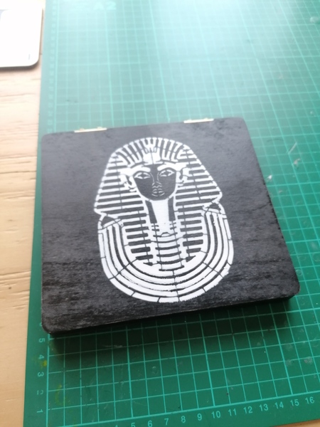
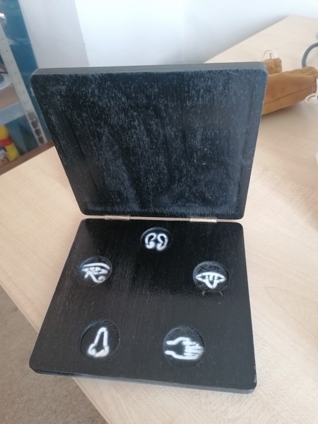
I have invented a new magic trick. It involves a very thin wooden box with 5 locations for coins inside, each labelled with one of the 5 bodily senses. A spectator places a coin inside, without telling the magician where it is. The magician then makes a show of listening to the box, sniffing the box, etc., and successfully determines where the coin was placed.
It has electronics hidden inside the wood which can detect the coins and then transmit the readings over Bluetooth, which are then picked up by my Bangle.js smartwatch, which vibrates to indicate the location of the coin.
It uses what I believe to be 2 novel innovations in magic:
- a method for detecting coins through solid wood that can be packaged extremely thinly
- a method for making sheets of plywood with electronics hidden inside
Presentation
The box is fully examinable by the audience. For them to prove that it is not made out of ordinary plywood they would need to either take the hinges off, or somehow X-Ray it. It is otherwise indistinguishable from ordinary plywood. I thought that this would make it an extremely powerful trick.
However it might be more of a "magician fooler" than a genuinely good trick, because a lay audience just needs to think "the box is rigged" to think they've figured out how it works. Sadly we'll never know how good it actually is as a trick, because I don't know any actual magicians who might be able to perform it. I have performed it myself for friends a handful of times but it did not get the kind of reaction I was hoping for. I don't know how much of that is because it is obvious that the box is rigged, and how much is due to my poor presentation.
I have been reading The Jerx magic blog lately. It has a lot of really good information about performing magic in a social setting. The key idea is that instead of doing overt magic "performances", you want to be secretly setting up magical moments that you act like you weren't responsible for. That way you avoid creating a division between the audience and the performer, and it fits more naturally in ordinary social situations. It works much better than having everyone pause the party to watch you stumble through your unnecessarily-long lecture on Egyptian faith healing. Or so I imagine.
Detecting coins
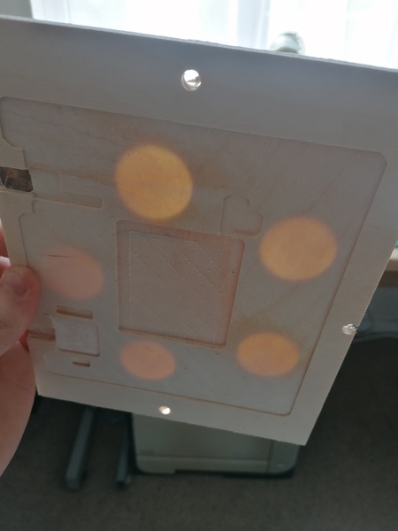
The most interesting part of the trick is how it detects the coins. There is a copper plate underneath each coin location, and another copper plate above. These plates form a capacitor, but the gap is quite large and the capacitance is extremely low. When a coin is placed in between the plates, it acts as if the plates have been brought closer together, and the capacitance increases. By measuring how long it takes to charge up the capacitor, you can tell how much capacitance there is, and therefore whether or not there is a coin in between the plates.
I prototyped this with a pair of 3d-printed parts. Each part holds a piece of copperclad board, and one part has a cutout for the coin.
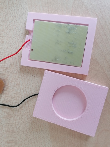
It worked well enough to convince me that I could proceed.
Making plywood with electronics hidden inside
You can make plywood with electronics hidden inside by starting with 2 pieces of plywood that are half the thickness you require, milling out a pocket for your electronics, gluing the electronics inside, and then gluing the two pieces together.
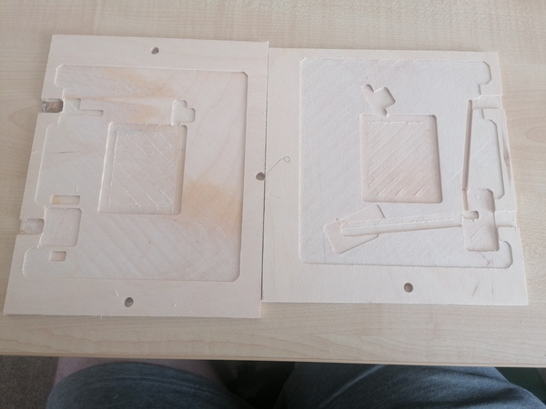
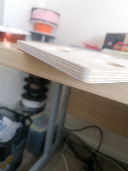
You'll want to make sure that the mating faces have perpendicular grain directions. And once the two pieces have been glued together, you'll then want to cut your piece of magic-plywood down to the actual shape you require so that the join is seamless.
Now you have the problem that your battery is glued inside the wood and you can't access it to charge it. I left a small gap in the wood through which I can poke a USB-C charging cable, hidden behind one of the hinges.
Gluing a lithium battery inside a piece of flammable material is probably a safety hazard, so I put a 1A "polyfuse" on mine. This is a type of fuse that automatically resets after some time has passed, very handy since I wouldn't have any way to replace a blown fuse. 1 Amp is way more than I actually need, a lower current rating would probably be better.
Implementation details
Capacitor plates
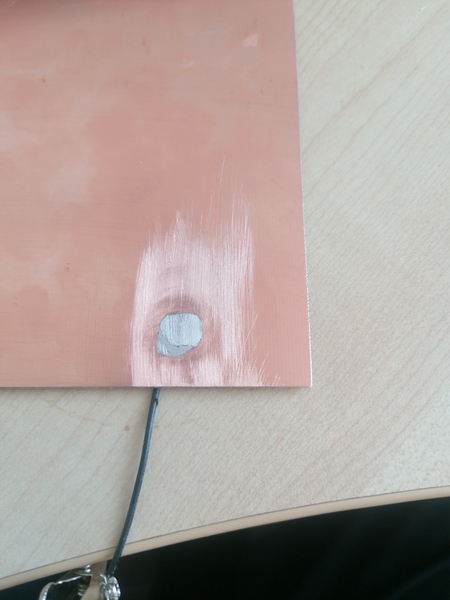
Putting the copper plate underneath the coin is easy, I made a circuit board with the CNC router:
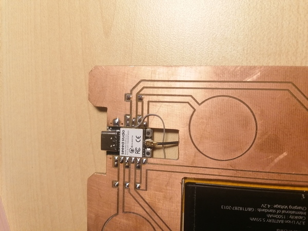
But how do we get a copper plate above the coin? I put a solid sheet of copper connected to a common ground plane inside the lid of the box, and conducted it to the ground plane of the main PCB through the hinges of the box! The solid sheet in the top has a wire soldered to it which is soldered to one of the hinges:
And the PCB on the bottom has a pogo pin to connect its ground plane to the hinge:
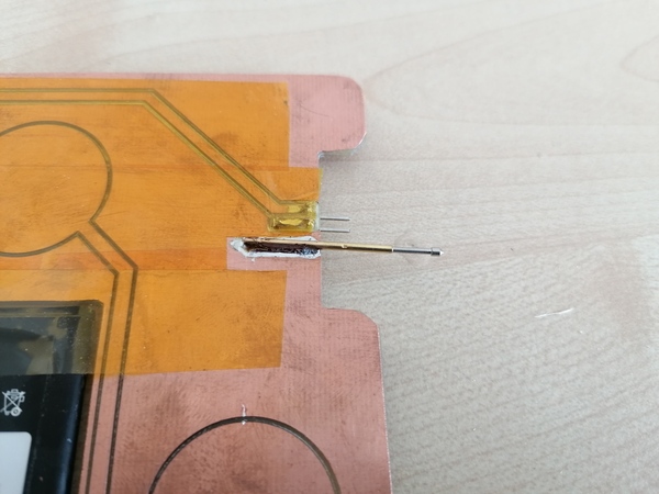
(Why not solder that one as well? I wanted the hinge to be removable so that I can access a pin header to disconnect the battery).
Circuit board
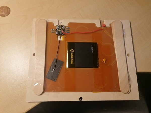
The microcontroller I used is a Seeed Studio Xiao ESP32C3. It is a good choice because it is very small, and it has a built-in Bluetooth radio, and a built-in lithium battery charging controller. That meant I hardly had to put any components on the board:
We have the microcontroller board, rectangular sticky-back Bluetooth antenna, 5x 1-Megaohm resistors for the capacitor charging circuits, a grey bodge wire (see below), a red wire connecting the battery charging circuit to the positive terminal of the battery, a pogo pin, a pin header to disconnect the battery, the battery, and a polyfuse.
Measuring capacitance
The Arduino code I use for measuring how long it takes to charge up a capacitor is:
int sensor(int n, int m, int sendpin, int recvpin) {
  int counter = 0;
  for (int i = 0; i < n; i++) {
    digitalWrite(sendpin, HIGH);
    for (int j = 0; j < m; j++)
      if (!digitalRead(recvpin)) counter++;
    digitalWrite(sendpin, LOW);
    for (int j = 0; j < m; j++)
      if (digitalRead(recvpin)) counter++;
  }
  return counter;
}
n sets the number of times we charge it up/down, to help with averaging the result. m sets the number of loop iterations we wait for it to charge up/down, sendpin is the pin that is connected to the "positive" capacitor plate through a 1-Megaohm resistor, and recvpin is a pin connected directly to the positive plate (the negative plate is tied to ground).
As the charge current slowly trickles out of the sendpin and through the Megaohm resistor, eventually the plate will get charged up enough that the recvpin goes high. In principle we could stop the loop as soon as the pin goes high, but in practice I found the readings to be quite noisy. Running a fixed number of iterations and counting how many the pin is low for works better. I also found it useful to measure how long it takes for the capacitor to discharge. You need to wait for it to discharge regardless, you may as well get some data from it.
If you use a Seeed Studio Xiao ESP32C3: don't try to use pin D9, it is internally connected to ground through a 300 kOhm resistor, which means you can never charge the capacitor up enough for it to work. I fixed this by disconnecting that pin from D9 and ran the grey wire to connect it to D0 instead.
Bluetooth
For some reason I was unable to make the ESP32 and the Bangle.js reliably connect to each other over Bluetooth. There was some speculation on the Bangle.js forum that this was caused by one of the devices being slightly out of spec on the Bluetooth timings. I don't know what the problem is. But since I only needed one-way communication, I had an ingenious solution.
Instead of connecting the watch to the ESP32 to receive sensor readings, I made the ESP32 write the sensor readings into the "manufacturer data" field of its Bluetooth advertisements! The watch can then read the values out of this field without ever having to actually "connect" to the ESP32.