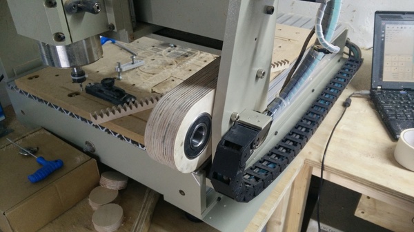
I've built a weird rotary axis for my CNC machine. Rather than a "4th axis" driven by its own motor, this one is geared off the motion of the gantry. It's still only a 3-axis machine, and there are no electronics changes at all. As the gantry drives back and forth, a toothed rack on the table causes a matching gear to rotate. The gear holds a chuck, which holds the work piece, so that when the gantry moves the work piece rotates.
And here's a video of surfacing the face of the gear so that the chuck can be mounted square:
I made this rotary axis because I have a new puzzle design which I want to make out of metal, and it requires machining all the way around a cylinder.
Why not a traditional 4th axis?
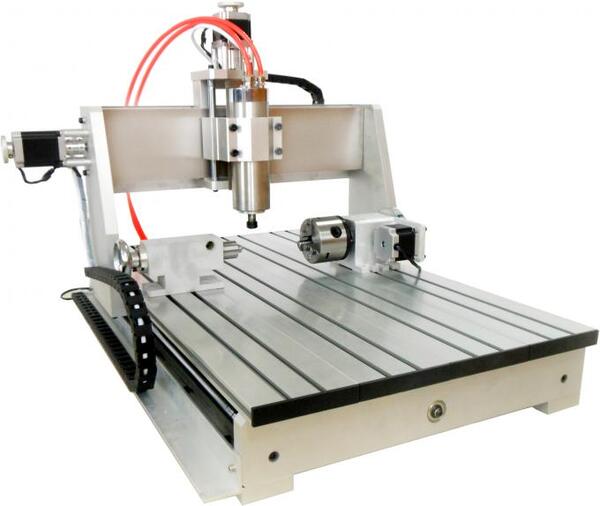
A 4th axis is normally mounted on the table, and controlled by its own stepper motor, independently of the other 3 axes:
I initially wanted to build a real 4th axis, but decided it was too much trouble, because Grbl only supports 3 stepper motors. There are Grbl derivatives which can do more, but they require more capable hardware than an Arduino Uno, and I can't be bothered rejigging all of the electronics. So my next thought was to use the Y-axis stepper driver to control a rotary axis. When I wanted to use the rotary axis I would unplug the Y motor and plug its cable into my 4th motor. The downside is that I would still need to acquire a 4th motor.
Then one morning, while lying in bed, I was pondering some more on how to do this. I had some ideas about disconnecting the gantry from the leadscrew, and adding a bunch of bevel gears, with a shaft driven off the leadscrew, running vertically up through the table, but then it occurred to me that I could leave the gantry connected to the leadscrew and control the rotary axis with the gantry's movement relative to the table! This seemed like much too weird an idea to pass up, so I was compelled to implement it.
I wrote a few paragraphs about the idea to some friends, and in a post on reddit, but mostly people either didn't understand or didn't think it was a good idea. One person linked me to a Perry Projects blog post from 2017 with the same idea, which was quite encouraging.
Design
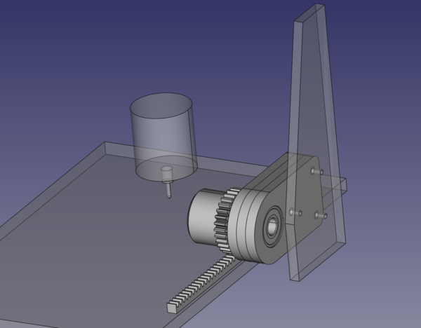
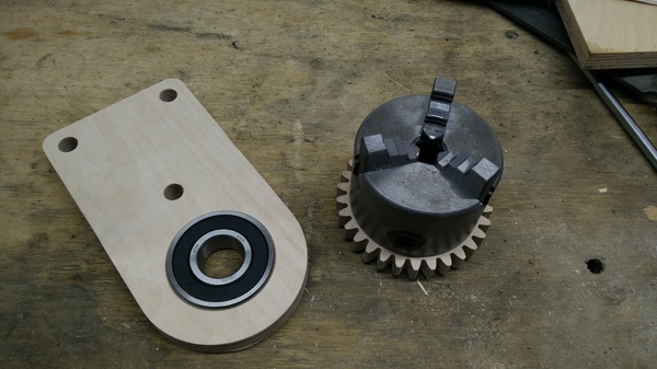
I took some measurements from the machine, modelled the important pieces in CAD, and then designed the rack, gear, and mounting plates to match:
The 3 bolt holes in the mounting plates are deliberately oversized, to provide wiggle room for alignment. I need to be able to slide the plates up and down to ensure a tight engagement of the gear teeth (I don't want any free play at all), and I need to be able to slide them forwards and backwards to ensure that the spindle is centered on the centre of the cutting tool.
The gear has a step in it to fit the recess in the back of the 80mm 3-jaw chuck from my mini lathe.
The shaft is made out of what's left of a pneumatic cylinder I made a few years ago, it was chosen because I have already cut a thread on one end, and it was almost the right diameter to suit 2 large bearings that I already had.
Finally (not pictured) there is a 3d-printed spacer behind the gear to provide clearance for the nuts holding the chuck, and a 3d-printed "bung" to screw up the end of the shaft to prevent it from falling out. Ideally there would be a spacer between the 2 bearings but I had already pressed them in by the time I thought of this. If this proves problematic I can always knock one of them back out and fit a spacer in future.
Build
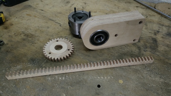
Making the plywood parts is easy, it's just normal CNC work. They're made out of offcuts of Russian Birch plywood that I bought for my SCAMP case. I really like this material, it leaves a nice crisp cut with very little tearing. There are only 5 parts: the gear, the rack, and 3 identical plywood plates, with a bearing pressed into each of the outer plates.
The gear needed 2 setups (top side and bottom side), because there is a step in the front to fit the chuck, and there are also recesses in the back for the nuts to sit in. In hindsight I could have done it in a single setup: I could skip the step in the front because I needed to re-cut this later anyway.
I don't have any pictures from making the shaft. It is a steel tube with a female thread on one end, turned down on the lathe to 25mm and lightly polished. It's worth taking your time getting this right as you don't want any play between the shaft and the bearings. I have a very agricultural "moving steady-rest" that fits this tube (which you can see in action here), but I still got quite a lot of chatter, so polishing the surface was really necessary.
Most of the squareness requirements are provided "for free" because the plywood surface is already flat (enough), and the gantry is already parallel (enough) to the Y and Z axes of the machine. The only tricky part is making sure the shaft is properly perpendicular to the gear. If it's not, then the gear will wobble as the shaft rotates and so will the work piece.
I didn't have a good plan for fixing the gear to the shaft. I just dripped a load of superglue in the hole and then pressed the shaft in with the vice. It is a good tight fit and seems secure, but unfortunately it was about 1° out of square, which was very disappointing, and I didn't immediately know what to do about it.
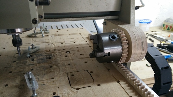
As I left the 3 plywood plates gluing up overnight, I realised that I could use the CNC machine to square up the face of the gear for me! I just need to drive the gantry back and forth with the cutting tool up against the gear, and it will automatically cut it square. What a relief! In some sense it was a blessing that I failed to glue the gear square to the shaft, because it forced me to come up with this alternative and superior method.
Next we need to bolt the mounting plates to the gantry. I cut out a cardboard template and aligned it with the approximate required position of the mounting plates, marked the holes on the gantry, and drilled them:
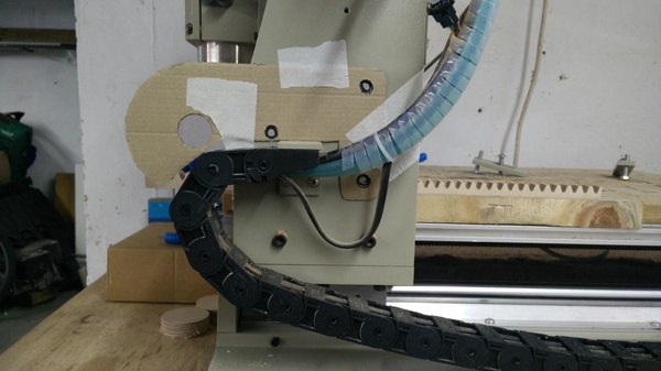
I drilled the gantry holes 8.5mm to accept M8 bolts, with the idea that I could drill this out to 10mm or 12mm if I need more wiggle room for alignment, but in the end I didn't need it, the oversized holes in the mounting plates were enough.
The rack is just screwed straight down to the table:
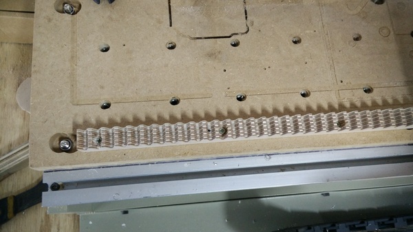
I was able to fit everything together so that the gear is nice and tight in the rack, and there is no discernible play in any direction, which I'm very happy with.
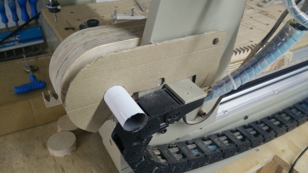
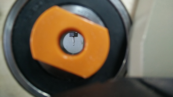
An unexpected benefit of making the shaft out of a hollow tube is that you can sight down the bore to check how it is centered on the cutting tool:
With the shaft installed, I surfaced the gear (shown in the video at the top) and fitted the chuck:
Next
Obviously the next step is to use this to make an actual part. I've only just finished building it, and so far the only cuts I have made were to surface the faceplate. I now need to write some software to turn my puzzle parts into G-code, and then I can try to make one out of a piece of plastic pipe, and only when that is successful will I try to make one out of aluminium or brass.
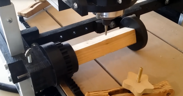
I'm not sure if I'm going to need tailstock support. Perry's Project uses a wheel that rolls along the table to support the far end of the work piece. Maybe I would do something similar:
Limitations
On a "normal" 4th axis, you can spin the part around and around forever, but with the one I have built there is a very limited range of motion, because if you try to move the Y axis too far you fall off the end of the toothed rack. This also means that we can't easily use traditional 4-axis CAM software, because it doesn't know that it has to "rewind" periodically to stop itself from running out of bounds. But my CAM software of choice is FreeCAD, and that doesn't support a 4th axis anyway.
We also can't do things like using this as an indexing head to machine flat features on different sides of a part, because the cutting tool is always centered on the axis of rotation.
Useful resources
If you want to learn about building rotary axes, you might enjoy watching This Old Tony's 4th Axis Build and CNC Lathe videos.
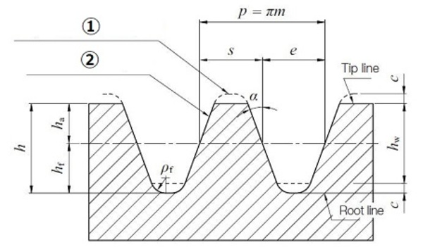
If you want to cut a toothed rack, then KHK Gears have a very useful page on the involute gear profile, including a diagram with all the important dimensions explained (apart from s and e, which I gather you adjust to get the tooth clearance you desire?):