
I've been struggling with generating complex toolpaths in FreeCAD and thought that an easy approach would be to render a heightmap of the part, and then generating a toolpath from that should be easy. I understand that this is already a recognised technique, although I could not find an open source tool that would do it for me. Most of the heightmap-related stuff I found on DuckDuckGo was to do with auto-levelling the bed. And, anyway, it's a relatively simple idea and a fun challenge, so I did it myself.
Get "pngcam" here: https://github.com/jes/pngcam. I don't think there are any serious "gotchas", it should mostly just work. But treat it with caution as it is under-tested and might make your machine crash into itself. The documentation is not amazing, but I expect --usage will tell you most of what you want to know. You can visualise the generated G-code by opening it in FreeCAD. Just initialise the Path workbench, then use "File -> Open" to open the G-code and you can explore it in 3D space in FreeCAD. It's worth doing this to make sure it looks sensible before you run it on the machine.
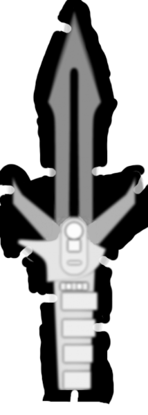
Here's an example heightmap (232x650 px) and the part I made with it (60x168 mm):
This post is comprised of two parts: Implementation and Usage. Implementation is about some interesting implementation details of pngcam, and Usage is about how I used pngcam to make the wooden Klingon dagger.
1. Implementation
1.1 Path generation
The basic idea is that we'll make the tool travel in a zig-zag pattern to cover the entire rectangle described by the heightmap, and we'll move the Z axis up and down at the same time so that we cut out the part.
The naive approach to this is to ignore the tool geometry and just take the Z height at a given X/Y coordinate directly from the brightness at the corresponding pixel of the image. Here's an animation of what happens in 2 dimensions with this idea. The blue thing with black stripes is supposed to represent a ball-nose end mill. The black line is the desired part geometry. The red dot is the point we've sampled from the heightmap image:

You can see that on a perfectly flat horizontal surface, the geometry is reproduced correctly, but where the tool needs to move up to clear space for a vertical feature, it doesn't move up until the centre of the tool touches that feature. This means features that raise up from a flat surface end up too narrow, and features that sink into a flat surface end up too wide.
Maybe this is fine! Maybe we could stop here. For some parts this would be perfectly acceptable, and for parts where it's not acceptable you could just add a thickness to the part equal to the radius of the tool, before rendering it to a heightmap, and then it would be cut out correctly.
But I wanted to do better, so I tried also sampling points at the very front and back of the tool (also the left and right side, in 3d, but not pictured):
I thought this would probably work acceptably, and it almost does, except for the tool-radius-sized chunk taken out of the top corners which I hadn't considered. (It also over-cuts surfaces that are anywhere between perfectly-horizontal and perfectly-vertical, with the worst case being 45°, but this isn't as bad as the chunk).
The solution is to sample every pixel in the heightmap under the footprint of the tool:

And then we precisely follow the desired surface without cutting into the part. Effectively this is adding together the heightmap of the part and the heightmap of the tool, and selecting the highest resulting height, which is the lowest point the tool can be moved to before it cuts into the part.
Unfortunately this is quite slow for high-resolution heightmaps because at every single step of movement we have to examine a tool-sized circle of pixels. For small stepover values, these circles would mostly overlap the previous ones, so we'd be computing almost exactly the same thing again, just moved over slightly. These overlapping subproblems suggest that a dynamic programming solution might exist, but I can't quite find one. For now I just keep the heightmaps low-res.
1.2 Path post-processing
The initial path is a series of points defining stepover-sized line segments that show where the tool must travel to cut away the unwanted material and not cut into the work. There are then post-processing steps to turn this path into usable G-code.
1.2.1 Roughing
You don't always want to cut the part to its full depth in a single pass, because this might either exceed the length of the flutes on the cutter, or might put an undue amount of stress on the machine. This is particularly problematic when cutting metals, but also applicable in wood and plastics.
To limit the maximum cutting depth, I added a "stepdown" parameter. If you pass --step-down 2 then pngcam will ensure that the tool is never cutting more than 2 mm into the material by performing multiple roughing passes first, cutting in all locations that would otherwise exceed the configured stepdown limit.
If stepdown is limited to 2 mm, then we'll generate a series of movements to cut everywhere that wants to be deeper than 2 mm, with the tool at Z = -2 mm, followed by another series of cuts everywhere that wants to be deeper than 4 mm, with the tool at Z = -4 mm, and so on until the full depth of the part is reached. These cuts are prepended to the initial path so that when the main path is executed, the depth of material that we cut into never exceeds the configured stepdown value.
1.2.2 Path segment consolidation
At this point we still have a bunch of line segments that are mostly only as long as the stepover setting. This would produce extremely long G-code files. In addition to the unwieldy G-code files, having lots of small steps prevents Grbl from being able to properly accelerate the tool. Grbl looks ahead 18 (I think?) G-code lines when planning its motion, but if the segments are very short then 18 G-code lines is not going to be very far in the future, so Grbl needs to limit the tool speed so that it can account for the 19th G-code line which might require it to rapidly reverse direction.
To solve these problems I made pngcam consolidate line segments by iterating over every point on the generated path, and removing points that lie on a direct straight line between the previous and next point, as illustrated here:

My initial approach for deciding whether 3 points were collinear in 3-space was to calculate the gradient of the 2 implied line segments in the X/Z plane and in the Y/Z plane and check whether the two X/Z gradients were equal and the two Y/Z gradients were equal (to within a reasonable tolerance). This mostly worked, except for the case where (during the roughing pass, for example) the tool is moved vertically down and then vertically back up: in both of these cases the gradients are 0, so it looks like we can safely discard the middle point, except obviously we can't because then the cut would not be performed. I solved this by checking the angle of the line segments with atan2 instead of the gradient, because this allows us to distinguish between up and down, and also checking the angle in X/Y in addition to X/Z and Y/Z.
1.3 Rapid moves
Pngcam uses the G-code commands G0 (rapid move) and G1 (linear move). "Rapid moves" are generally for moving the tool around between cuts, rather than moving the tool while cutting, and permit the motion controller to move in a non-straight line if it thinks that is faster. During the roughing pass, pngcam sometimes has to pick the tool up and move it over to somewhere else without travelling through the work in between.
I was moving the tool around using G0 to pick the tool up, then move it across, and then move it back down. Unfortunately, Grbl takes the view that it can do whatever it likes with rapid moves, so if it sees some consecutive rapid moves, it seems to discard the first ones and go straight to the destination requested by the last one. This does indeed move the tool to that position more rapidly, but it results in cutting a big gash out of the work piece! No bueno.
I solved this by using G1 for the steps that pick the tool up and move it back down, and then it moved in the path I expected.
2. Usage
2.1 Generating G-code
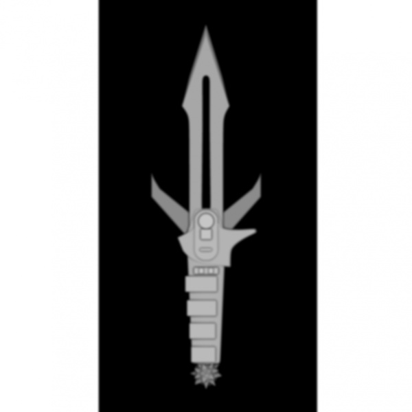
With the program ready, we need a test part. A little while ago I watched & enjoyed This Old Tony's CNC Sword video, so I wanted to make a sword as well, but I thought a small dagger would be a more sensible first attempt. I did a DuckDuckGo image search for various phrases like "dagger heightmap" and eventually found this "Klingon dagger" heightmap in a thread on RouterForums.com:
I modified it a little bit in GIMP to reduce the wasted cutting around the edges, keep the dagger attached with some retention tags, and reduce the thickness of the blade relative to the handle:
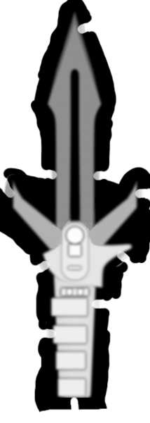
I also produced an identical copy of the heightmap, but flipped horizontally, for cutting the back side of the dagger. (I've since added a --x-flip option to pngcam to make this easier).
I thought I'd first rough out the shape with a 4mm ball-nose end mill, and then cut the detail with a 2mm one. In case you're interested, I invoked pngcam as follows:
pngcam --rapid-clearance 2 --step-over 2.4 --width 60 --tool-shape ball --tool-diameter 4 --depth 5 --xy-feed-rate 500 --z-feed-rate 200 --step-down 2 --clearance 0.1 --route both klingon-dagger.png > dagger-top-rough.gcode
pngcam --rapid-clearance 2 --step-over 0.6 --width 60 --tool-shape ball --tool-diameter 2 --depth 5 --xy-feed-rate 1000 --z-feed-rate 400 --route both klingon-dagger.png > dagger-top-finish.gcode
pngcam --rapid-clearance 2 --step-over 2.4 --width 60 --tool-shape ball --tool-diameter 4 --depth 5 --xy-feed-rate 500 --z-feed-rate 200 --step-down 2 --clearance 0.1 --route both klingon-dagger-bottom.png > dagger-bottom-rough.gcode
pngcam --rapid-clearance 2 --step-over 0.6 --width 60 --tool-shape ball --tool-diameter 2 --depth 5 --xy-feed-rate 1000 --z-feed-rate 400 --route both klingon-dagger-bottom.png > dagger-bottom-finish.gcode
So the idea there is to run dagger-top-rough.gcode with the 4mm tool, then switch to the 2mm tool and run dagger-top-finish.gcode, then flip the work over, reinstall the 4mm tool, and run dagger-bottom-rough.gcode, and finally switch back to the 2mm and run dagger-bottom-finish.gcode. dagger-top-rough.gcode looks like this, rendered in FreeCAD:
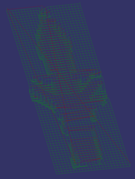
The red lines are G0 rapid moves, and green lines are G1 linear moves. Kind of hard to see but if you stare at it for a bit you might be able to understand what is going on.
2.2 Running the machine
If we only wanted to cut the dagger out of one side, we'd be ready to go, but since we need the cut on the back side to be aligned with the front side, we need a reliable alignment plan. My approach to this was to manually mark out the rough rectangle in which I wanted the dagger, then drill a hole in the top left. I then clamped the wood onto the bed of the router, roughly square to the X and Y axes, and zeroed the coordinates on the location of the hole I drilled. Relative to this hole, I then used the router to drill holes in the other 3 corners. Then when I flip the part over I can pick up the alignment by checking whether the locations of the holes correspond to the correct coordinates, and adjusting the position until it does.
I started with conservative feed rate parameters to check that it was working, and then increased the feed rate override to 200% in UGS Platform to run at full speed.
I have a short video showing what the cutting looks like on the second side:
And the end result is this:
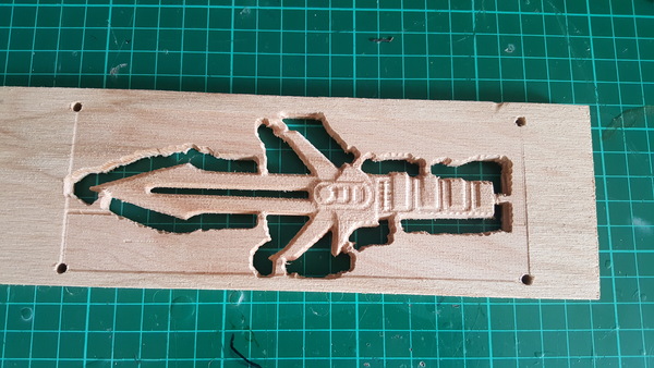
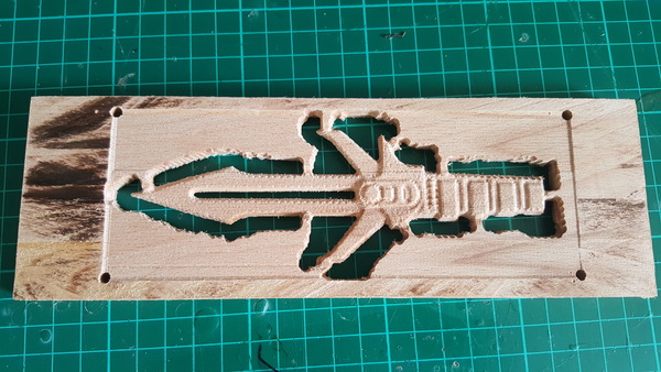
I was originally going to cut off the tabs to release the dagger from the plank of wood, but I have no use for a tiny wooden dagger, and I like how it looks still attached to the board it was cut from, so I think it is more interesting to leave it as is.
You can see there is one mistake: a vertical line cut too deep at the very top, about 1/3 of the way across. This was caused when the machine disconnected due to EMI and I failed to correctly realign the Z axis. I hit the emergency stop before it cut into the actual part, so no harm was done. I thought I had solved the EMI problem but it still happens occasionally, I'd like to get to the bottom of it. The USB cable I am using is shielded and has a ferrite choke on it, but maybe that's not enough? Or maybe the EMI is coming from inside the control box? Perhaps a grounded metal box around the Arduino would help? I'd be interested in hearing from anyone who knows about this stuff. Firstly on how to work out exactly where the EMI is affecting things, and secondly on what to do about it.
3. Next
With pngcam, I (and also you) have gained the ability to turn a heightmap into G-code. Sadly this is only one half of the puzzle: we also need a way to turn a CAD model into a heightmap. You can do this by loading the model in Blender and configuring Blender to render a heightmap, but that's quite inconvenient. I've been reading up on triangle rasterisation algorithms, and I've never implemented one before, so I think I am quite likely to write a software renderer which will take in an STL file and produce a heightmap. With that in place, we'd almost be able to operate the CNC router with the same level of ease as the 3D printer: just stick in an STL file and get out ready-made G-code. No manual toolpath planning required!
Obviously for certain part geometries, and particularly for engineering parts, it would be quicker and more accurate to use toolpaths generated with more traditional CAM software. For decorative parts, and complex shapes, I think pngcam might be a useful workflow. I actually started working on pngcam in the first place because I was challenged to machine an aluminium keyboard keycap but found myself unable to generate toolpaths for it in FreeCAD. The FreeCAD Path workbench is basically designed for generating cuts that either move the tool in the X/Y plane or in the Z axis. It is hard (if not impossible) to generate toolpaths that follow complicated surfaces. Hopefully this improves in future, but in the meantime I'm enjoying myself working on pngcam.