Last modified: 2025-06-25 13:35:57
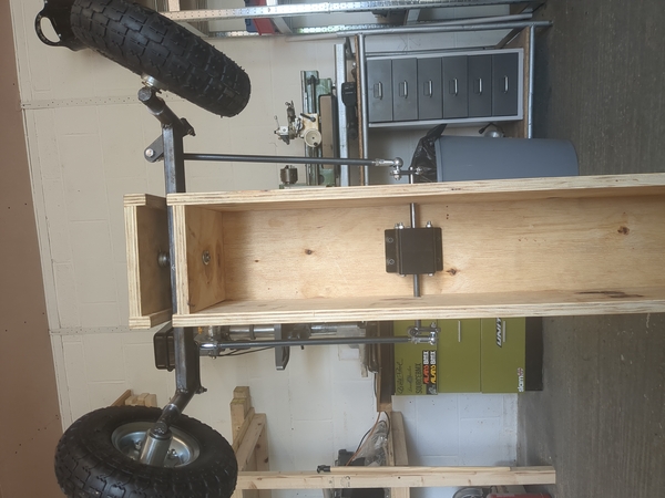
< 2025-06-23 2025-06-27 >I've got the track rods (?) made, and threaded, and installed:
To get the steering geometry right, you want the arms at the front to be pointing maybe 20° forwards, and the arms at the back to be pointing maybe 10° backwards, with the wheels pointing straight.
It takes about 270° of steering wheel motion for the arms at the back to "reverse" and start pulling the wheels back the other way.
I'm thinking I'll put a stop at the back side of the front axle (lower in pic), pretty much flush with the back side of the axle.
There is basically zero bump-steer. I think there is more play in the system than there is bump-steer, so you can move it through the whole range of swinging motion and neither the steering wheel nor the kingpins needs to rotate.
Still todo on steering is:
I'm trying to work out a good way to do stops without having to do any welding. Maybe welding is the easiest way. Also it would be good if they were adjustable.
For the outer bearings at the gearbox end, I am giong to make some sort of fitting that will bolt to the plywood and hold the bearing.
I guess 3d-printed is easiest.
They can stick out up to 30 mm from the plane of the side of the chassis.
I'm 3d-printing them.
And in the mean time I can try to rig up some stops.
I did this:
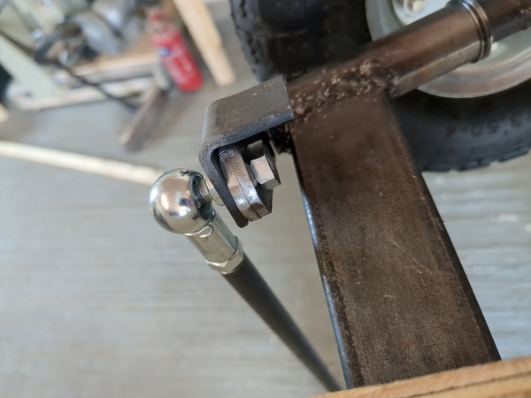
But it doesn't work very well, to get enough steering angle the arm at the gearbox end is almost pointing straight back, and then it can easily slip over and go around and around.
So the new plan is to constrain it at the gearbox end instead of at the front axle.
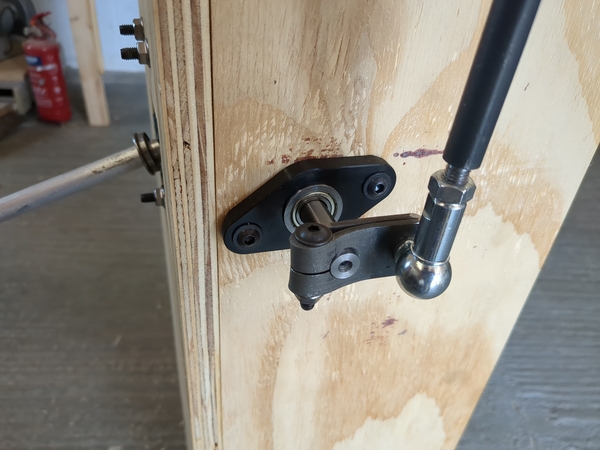
I ran out of PC-Max midway through printing these, but they're adequate as is I think. They were meant to look like this:
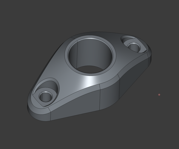
But they're just installed upside-down instead, with the infill facing the chassis.
So I think the plan is to stick a bolt through the chassis to catch the arm as it rotates, to prevent it from spinning all the way around.
An M12 bolt through each side of the chassis:
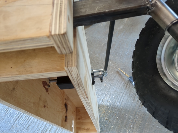
This works great.
The only thing left to do on steering for now is the real version of the input shaft. Steering wheel etc. can wait until later.
Moving on to the rear axle: I have cut it to length, need to turn the ends down to 19 mm.
I had thought that a 20 mm shaft would fit through the headstock, but sadly it doesn't.
So I have rigged up this:
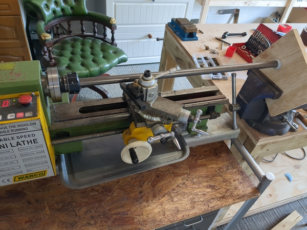
There is just a tiny bit of material grabbed in the collet, with another piece of material supporting the back end of the collet, and then a nylon bush in a piece of plywood clamped in the vice to support the loose end of the shaft.
It actually worked pretty well!
https://www.youtube.com/watch?v=NYwm7MIjHok
I just had 5 mm or so left on the end to reduce to 19 mm by hand with a file, which didn't take too long. Need to do the other end next, except now I'll have quite a sloppy fit in the nylon bush. Unsure whether to make another bush or think of something else. The metal that ran in the bush got quite hot last time so 3d-printing is probably out.
I made this today:
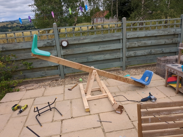
It is the old totem pole, swinging on a piece of 12 mm steel rod, in a quick and dirty frame, and with some primary school chair seats screwed down to the ends.
As seesaws go, it's not very good. It is too short and too high, and there's nothing to hold on to.
< 2025-06-23 2025-06-27 >