Last modified: 2025-05-05 15:07:44
< 2025-05-04 2025-05-09 >I'm going to try to simulate curved resting surfaces. I think by approximating it as a polygon with many short segments. That also means there is a natural interpretation of the "resting surface locking angle". Every line segment should be offset from the tangent by that angle.
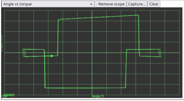
I've just spotted that "lock safety" isn't working properly. With lock safety set to 0, you should land on the opposite pallet at exactly the same angle as that pallet starts impulsing, but the plot looks like this:
Some good notes on escapement layout in 20240503.md.
But it looks like the code is right, I don't understand where the extra lock safety is coming from. I could try setting negative values for lock safety and see what makes it act like it's genuinely 0.
About -0.085 degrees. That doesn't obviously match any of the other parameters.
Changing lift and drop doesn't change this value. Changing tooth span from 12.5 teeth to 10.5 teeth changes it from -0.085 degrees to -0.16 degrees.
I think the entry pallet impulse surface should be the same as the exit pallet impulse surface but mirrored across Y axis.
Err... no, that is wrong.
The issue is that the torque impulse face is not centered on the 0 anchor angle even when lock safety is set to 0.
Oh! It was caused by the linearSlop setting in Planck.js! I've changed it from 10e-7 times majorDiameter to 10e-8 times and now it is much better.
majorDiameter is 55 mm, 10e-7 times that is surely a negligible length? How does this cause so much difference? Unsure, but reducing the allowable slop
solves the problem.
Well that's sorted, what about curved resting surfaces?
I think we work out how many segments we want, divide the resting surface length by that number, and then stack up that many segments the same way we currently add just the first segment?
There is a dramatic discontinuity in the torque at the boundary between the segments:
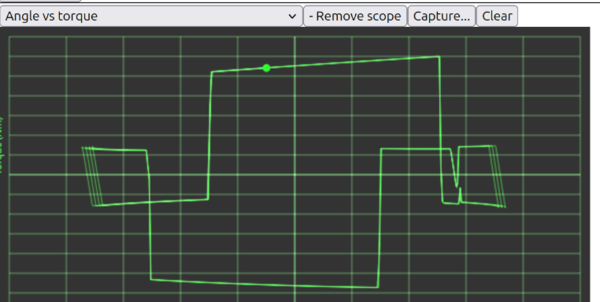
Just to see if it would work I made the entry pallet (right-hand side of diagram) out of 2 segments instead of 1, and you can see it has big spikes in the torque plot. So I think this method isn't going to work. So if we wanted to simulate curved resting surfaces we'd need to write the physics code manually.
However I think an analytical solution should be relatively easy. We can assume that the drop takes 0 time and the escape wheel has 0 moment of inertia, so no bouncing etc. And then we work out geometrically whether the escape wheel tooth is on the impulse face or the resting face, and then apply torque to the pendulum accordingly.
And I think ignore any unwanted interaction between the anchor and the sides of the escape wheel teeth, avoiding those collisions is up to the operator. Or maybe we detect the collision and warn about it but don't try to calculate any physics for it.
Another cool thing to do would be to automatically search for an escapement configuration that is as isochronous as possible with respect to changes in coefficient of friction, drive torque, pendulum Q, etc.
So what would the process look like?
Comparing to the existing simulation code:
When the pendulum has positive angular velocity, it is engaged with the exit pallet until the end of the exit pallet impulse.
Exit pallet impulse ends at a pendulum angle of lift/2 + locksafety. For angles greater than this, the entry pallet is engaged.
When the pendulum has negative angular velocity, it is engaged with the entry pallet until the end of the entry pallet impulse.
Entry pallet impulse ends at a pendulum angle of -lift/2 - locksafety. For angles less than this, the exist pallet is engaged.
For the exit pallet, it is engaged with the impulse surface for angles above -lift/2 + locksafety and the resting surface for angles
below that.
For the entry pallet, it is engaged with the impulse surface for angles below lift/2 - locksafety and the resting surface for angles
above that.
We know the drive torque. The force at the tip of the escape wheel tooth is drive torque divided by radius to tooth tip.
Then what proportion of that force is transmitted tangent to the pendulum? I guess work out the direction that the force is being transmitted (tangent to the escape wheel) and somehow project that onto the pallet surface? And then you'll get a component acting tangent to the rotation of the pendulum, and a component acting radial. I think ignore the radial component, and turn the tangent component into a torque based on its radius from the pendulum pivot.
ChatGPT says:
F_total = drivetorque / escapewheelradius (scalar, but make it a vector in the direction tangent to the escape wheel at point of contact)
palletnormal = vector normal to pallet surface at point of contact
F_transmitted = (F_total dot palletnormal) * palletnormal (vector)
pendulumtangent = vector tangent to pendulum rotation at point of contact
F_effective = F_transmitted dot pendulumtangent (vector)
palletradius = distance from point of contact to pendulum pivot
torque = F_effective * palletradius (scalar)
ChatGPT:
palletvector = unit vector in direction of pallet surface, in the direction of escape wheel tooth movement (vector)
F_friction = -mu * (F_total dot palletnormal) * palletvector (vector)
torque = (F_friction dot pendulumtangent) * palletradius (scalar)
ChatGPT:
torque = -m * g * L * sin(theta)
Total torque = sum of 3 torques
angular acceleration = torque / momentofinertia
And then updating angular acceleration and velocity is trivial.
So is that a complete solution?
Not quite, because I still need to find the unit vector in the direction of the pallet surface in the direction of escape wheel tooth movement.
It would probably be OK to always take that vector in the same direction, abs() the torque it creates, and always apply that torque in the direction
that would oppose the motion of the pendulum.
We also need to know the point of contact between a pallet surface and an escape wheel tooth. Once we've worked out which surface is active, we find the point of contact by intersecting that surface with a circle centered on the escape wheel centre.
To find the vector normal to the pallet surface, we just add 90 degrees to the angle of the pallet surface?
To find the vector tangent to the pendulum, we find the angle to the point of contact and add 90 degrees to that?
And then I think that is all.
< 2025-05-04 2025-05-09 >