Last modified: 2025-03-10 21:25:50
< 2025-03-09 2025-03-11 >Let's try and add a "thickness" operation. It should let you say whether the thickness is inside, outside, or centred on the existing surface.
"Delete this" on a subtraction is deleting the second child instead of reparenting it to the parent.
It's because I was passing a reference to the node.children array, which they're
then getting deleted from, so the length changes mid-loop as they're being added
to the new parent. Solution is to shallow clone the array.
There is some sort of glitch if you have a Transform node with no children, or if you disable a Transform node, and it is a child of a smooth union.
I think the issue is that smooth union of some shape and a noop is broken, instead
of just being the one shape. Is it just a numerical error because the noopShaderCode() is such a large number? Yes, I think so. Reducing the noopShaderCode() from
10000042.0 to 142.0 has fixed it.
But that is not ideal because you might want features bigger than 142 mm, and the "noop" object should never appear to be closer to the surface, for example when applying a thickness.
Cursor has solved it by adding explicit tests to the combinators to see if the child code is noop code, and skipping over the child if so.
When it is recompiling the shader it lags the user interface. We should try to do that in a web worker or something?
Ah, but I don't think you're allowed to do web workers with a local HTML file.
OK, it's even easier than that. You just sprinkle async and await around and
it magically works!
For some reason we're recompiling the shader again when you click off the property editor. The document is getting marked dirty.
The PropertyEditor is calling onPropertyChanged() when you remove focus.
One fun idea is we could bundle the entire application with saved work, and then give you the option to load it up in the same version that saved it, even if breaking changes are made in the "real" version.
I'm implementing JavaScript versions of the SDFs. This has meant bringing in vec3.js
and mat3.js, and I also need to make sure that all of the "vector" properties of
the nodes are actual Vec3 objects.
Once I have finished adding JavaScript implementations, it might be good to have a toggle to turn on software rendering, just to check that the JavaScript implementations are correct.
And then we can do things like:
But actually, thinking a bit more... we could definitely export the depth under the cursor via the fragment shader one way or another - could we get the GPU to do marching cubes?? Then we only need the GLSL implementation of the SDF and no duplicate JavaScript one.
If you wanted to evaluate the shader at every 0.01mm inside a 100mm cube, you'd have 10^12 evaluations, which at 24 vertices per pixel would be about 200000x200000 pixels, or 5000x 4K frames. If we are at 60 fps rendering 4K then this would take 83 seconds.
Is there a better option than evaluating the SDF at every vertex within the space? Can we make the vertices denser where the SDF is closer to 0?
This reddit thread talks about Octrees for SDFs: https://www.reddit.com/r/VoxelGameDev/comments/ontjdf/how_is_sdf_stored_in_a_octree/
The SDF is, as you say, a continuous function. Continuous functions can be approximated by interpolating values on discrete intervals (grid etc.).
So we set an acceptable error value, start by constructing our octree with the first 8 nodes, sample, check the interpolated values at the positions of the child nodes, and if the error is too large we refine the node by creating the child nodes and adding the real values, then repeat.
So let's say we start out with our octree being a single cube that contains our entire object. Evaluate the SDF at the corners, then split the cube into 8 child cubes, and evaluate the SDF at the new corners. If all of the new evaluations are within some acceptable tolerance of the interpolation of the parent cube evaluations, then we discard the child cubes and stop. Otherwise recurse until some limit. And then you have a sparse voxel octree of your SDF, and when you do marching cubes on the sparse voxel octree you have much fewer vertices to deal with.
How do we do that on the GPU? Apparently compute shaders are available in WebGL 2. So I should hold off on JavaScript versions of the SDFs, might be able to do it all on GPU. Maybe compute shaders aren't available, I am reading conflicting information.
WebGPU is the successor to WebGL apparently, but it is not yet available in Firefox. However it would be possible to ditch the model of running in the browser and instead run in Electron.
Another idea is can we compile GLSL to JavaScript? Then we can run marching cubes or whatever in JavaScript, but not have to provide 2 implementations of the SDFs.
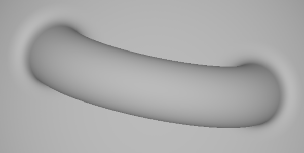
I'm going to try to get Cursor to make the fragment shader do multi-sampling anti-aliasing.
Before:
After (4x4 MSAA):
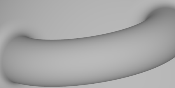
Good.
A polycurve is like a polygon except it can have arc segments.
A sketch is a bunch of 2d polycurves that the user can manipulate by dragging the associated vertices.
(Later on we'll add a constraint solver to the sketch system).
If all of the 2d polycurves are actually closed, then the sketch is "valid" and then we can make a 2d SDF of it.
We can attach the sketch to a plane.
With the sketch attached to a plane we then turn it into a solid either with a linear extrusion or a revolve. (Later on we might be able to sweep along a path composed of polycurve parts). To do a "pocket" we'll just make a positive part and then use Subtraction.
So we'll need:
So let's just hardcode the planes to XY/XZ/YZ, and hardcode an initial polycurve?
Current status is I have committed code to implement this but it's not working properly.
So:
sdf() functions, revert the previous commit if notI'm going to see if I can print a new set of gears that will fix the ratio.
And, watching myself work, I'm using:
I think I can safely go up from 10 teeth to 19 teeth on the pinions, which would mean going down from 40 to 31 on the larger gears. So that's changing from 4x ratio to 1.63x ratio. Two lots of that changes from 16x to 2.66x, which reduces the overall ratio from 64:1 to 10.64:1, which is about what ChatGPT said we want.
I did have trouble installing the pinion on the flywheel shaft last time, so I'm going to shift stuff around a bit to make it easier.
Printing these 3:
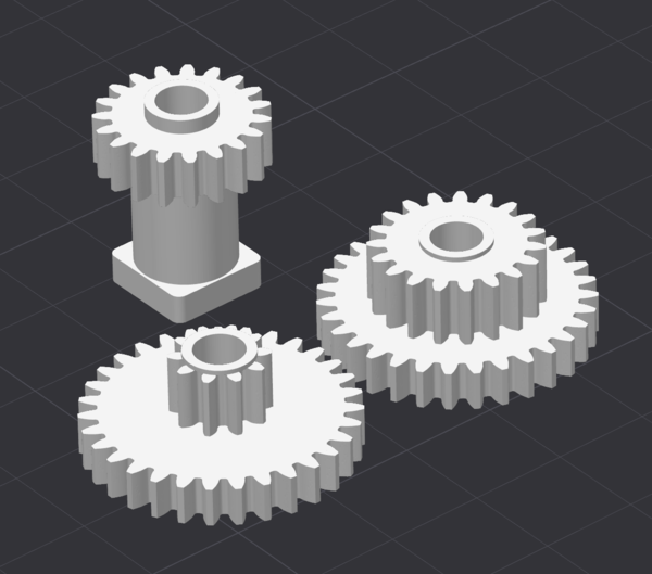
I'm not going to bother switching to the 0.2mm nozzle.
Whoa, it works!
https://www.youtube.com/watch?v=7bHLnYVaxe0
So good. I should have listened to ChatGPT in the first place.
requestAnimationFrame() if the pan/zoom/document etc. has changed, no need to redraw the same frame over and over againsmoothK be renamed to blendRadius? filletRadius? If it doesn't act like a radius, can we make it one? If not, what else should we call it?smin() function in fragment.js, and also add a similar one for chamfers, and use if (abs(d1) < k && abs(d2) < k) return d1+d2-k; else return min(d1,d2); as smoothmin but for chamfers - and any code that has an option to do a smooth min (which should be everything that does any kind of explicit or implicit union), gives you the option to add a blend radius, and decide whether it is filleted or chamferedroundRadius?