Last modified: 2024-05-03 16:58:24
< 2024-05-01 2024-05-05 >I still haven't reread the section in the book, but I was thinking overnight.
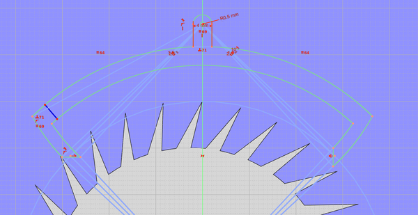
I think you draw a circle at the diameter of the tips of your escape wheel teeth (the tips are the only part that interact).
Decide how many teeth you want the anchor to span (I think in the book they said this should be halfway between 2 teeth, for example 7.5).
Divide that by the total number of teeth to work out what fraction of the wheel you are spanning, and therefore what angle. 7.5 / 30 = 0.25, or 90 degrees.
Imagine a 90 degree sector of the escape wheel, centred on the Y axis. Where the sector arms meet the escape wheel diameter is where your pallets are going to be.
Imagine tangent lines to these points, where the tangent lines intersect the Y axis is your anchor pivot.
(Is this point where the start, middle, or end of the impulse occurs?)
And then for definitions I think:
So let's say we want 4 degrees lift (I think the book said 4 degrees was sensible? can't remember), and let's say that the points at the end of our sector arms are the middle of our impulse.
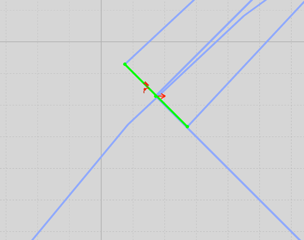
So now imagine 2 line segments passing through our anchor pivot, but 2 degrees either side of the tangent line (for 4 degrees total). These line segments are the same length as the length between the anchor pivot and the point where the pallet interacts. That means that they will meet the escape wheel at the same place, but when the anchor has rotated +/- 2 degrees.
You'll notice 1 line is clear of the escape wheel teeth and one line interferes with them, this is what we want. Now draw a line segment connecting the endpoints of these 2 segments. That line segment is your impulse pallet.
So how do we look at this point?
OK, no good:
That puts our pallet face almost radial to the escape wheel, obviously, which is no good.
OK, alternative plan. Given that we know how much "drop" we want (let's say 2 degrees), and we know how large is the angle between adjacent teeth (360/30 = 12 degrees), then we know the impulse needs to span 10 degrees. So we can draw a 10 degree sector centered on the radial line on the escape wheel, and the intersection of the arms of that sector will intersect the lines at +/- 2 degrees of the tangent:
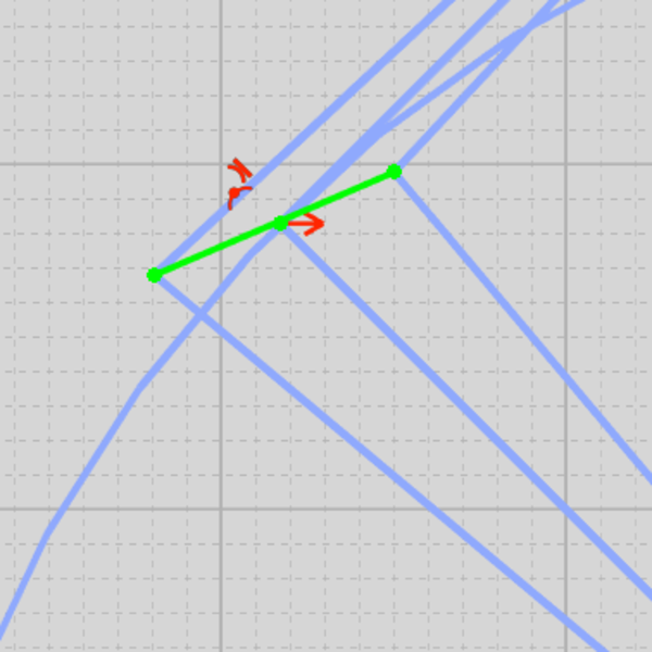
Much more convincing!
Now we need to draw an arc at the left-hand edge of this pallet face, centered on the anchor pivot, and that's our frictional rest pallet. It needs to be long enough that at maximum amplitude the escape wheel doesn't fall off it. Let's say maximum amplitude is 20 degrees, make this arc join up with a line 20 degrees away from the tangent line:
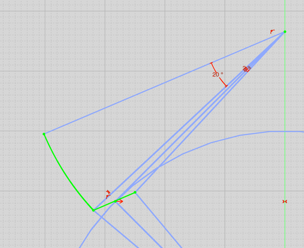
Very good, that's the entry pallet working faces done.
Now what if we do the same for the exit pallet?
Looks believable I think. And this is the anchor in the dead centre position.
Obviously there is some freedom in terms of which parts you make line up. For example I have made the impulse faces centered on the point on the escape wheel diameter that I care about, symmetrically, but you might alternatively want to make the locking faces equally far away from the anchor pivot, or you might want to go halfway between the two options, or something else. This definitely wants to be configurable in the simulator.
I'm going to draw a quick escape wheel in FreeCAD and check that this escapement looks like it would work.
No, it looks like something is wrong. I think the impulse faces are too long:
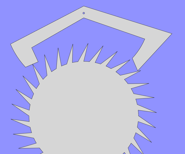
You can see that a tooth is engaged with the entry pallet impulse face, but another tooth is already at about the right place for locking on the exit pallet.
Was it a mistake to make the impulse faces span 7.5 teeth? Maybe it should be an integer number.
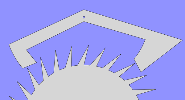
7/30 = 84 degrees, let's try that.
Obviously wrong, because it means when a tooth is at the centre of the entry pallet impulse face then another tooth will be at the centre of the exit pallet impulse face, so it can't possibly work.
Oh! By making the impulse face span 10 degrees, with 2 degrees drop, I am basically saying that when a tooth escapes a pallet, I want there to be already another tooth dropping onto the same pallet. That is not right, I want the next tooth to drop onto the other pallet. So instead of saying I have 12 degrees between teeth, I think I actually say I have only 6 degrees between teeth, because they drop onto the pallets alternately. So the impulse face should span only 4 degrees.
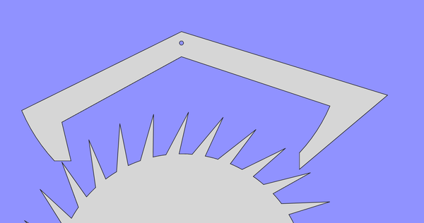
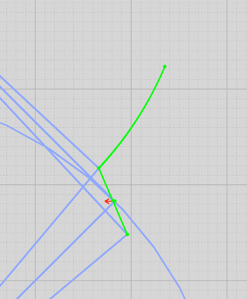
Looks perfect. Playing around with rotations in FreeCAD, it looks like it works almost exactly perfectly, except that at the point where a tooth escapes, the next tooth lands at the very corner of the other pallet, instead of landing safely on the locking face.
So I think that says that we want the impulse pallet to be biased to be slightly after the tangent line. If I change +/- 2 degrees to 2.5 on one side and 1.5 on the other, does that look better? That now means that the impulse will be biased slightly after the dead centre position of the pendulum.
Yes, perfect, this seems to work well now. So one of our parameters is "locking safety angle", there's probably a better word for it.
So the obvious parameters are:
And maybe to allow biasing the difference between "equal length from anchor pivot to impulse face" and "equal length from anchor pivot to locking face", we just change the sector of the teeth we span. Instead of making it symmetrical, you could rotate it slightly to the left to push the entry pallet further from the anchor pivot and slightly to the right to push the exit pallet further from the anchor pivot. Would you call that a "sector offset angle"?
So I can use the info above to calculate the geometry for the impulse faces and locking faces. But how do I turn that into a solid object?
Firstly, the locking faces need to be broken up into a series of straight lines, because I can only specify polygons. Secondly, the exit pallet locking face will probably need to be multiple polygons because I can only specify convex polygons. And thirdly, I need to give the parts some thickness.
I saw this Graham's deadbeat escapement model:
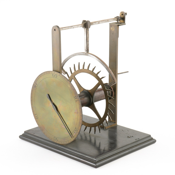
That looks quite smart (albeit that it doesn't look right - isn't the anchor pivot much too far from the escape wheel?). We can make it look like that by letting the entry pallet's locking face get longer, and then laying the rest of it out with arcs centered on the escape wheel and anchor:
Why would you want the pivot to be further away than the intersection of the tangent lines? Would you want that, or is it just an error? And, if you do want that, how would you express it in the simulator? Add a parameter for "anchor pivot offset"?
< 2024-05-01 2024-05-05 >