Last modified: 2023-12-04 20:45:48
< 2023-12-03 2023-12-06 >I took another measurement of the beech clock delay vs the plywood clock. After a total of 22h47m00s, the beech clock is 2m3s behind, or 0.15% slow, which suggests a gearbox ratio of 1:16.024. I don't have a great solution for correcting this ratio.
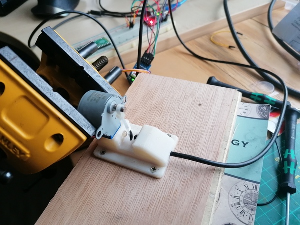
I have made a quick-and-dirty test setup to measure the actual ratio:
There is a cable tie on the motor, with a rubber foot on the end to make it interrupt the beam better. I'm not doing any data processing on the Arduino, just dumping out the step counts at which the beam is interrupted, and then I'm going to process it in Perl.
First indications from the Perl script are 1:16.032, which is good news. Not sure how legit that is though.
I plotted how the implied gearbox ratio changes over time with the number of logged revolutions:
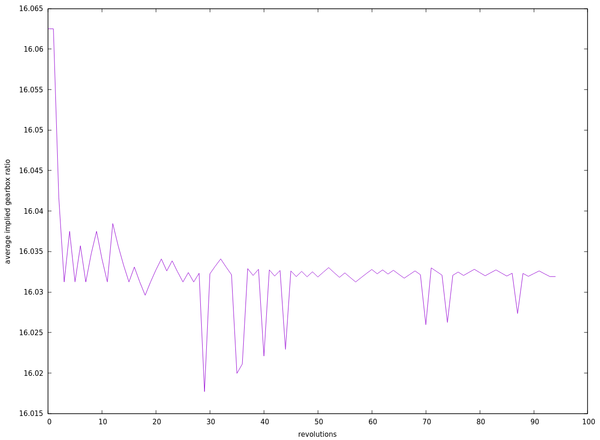
It looks like it is definitely converging to about 1:16.032, just need to run it for longer to get more decimal places.
This looks to be a much more effective way of measuring the ratio of these motors than comparing the two clocks. Not sure why though, maybe it is just too hard to accurately say when the minute hand is exactly vertical.
So on the assumption that it is in fact 1:16.032, what do I need to do?
I think the best train is 1:25 6:43 6:47, which makes it lose 5 minutes in 6 months. Obviously the 6:43 and 6:47 can be swapped if that is helpful.
The "1:25 6:..." is the same as what I've already got, so I can keep the existing first wheels.
I need to make a new second wheel with 43 instead of 45 teeth, but large enough to mesh with the existing first wheel pinion, keep the second wheel pinion as it already has 6 teeth, and make a new third wheel with 47 instead of 45 teeth, but small enough to mesh with the existing second wheel pinion.
So that is quite straightforward, only 2 gears need replacing, the changes are very small, and no pinions need changing, so it should be easy enough to make new tooth profiles that will work without changing the diameter.
I wet-sanded the white paint on the dial blanks & sprayed 2 coats of lacquer on them. I'm not going to try to do the engraving today, will wait for the lacquer to dry.
I think the chart might be converging on a ratio closer to 16.0323 than 16.0320, that's bad news. The best geartrain for 16.0323 is the same as the one for 16.0320, but it loses time twice as fast if the stepper motor gear ratio is 16.0323.
If we're allowed a few more teeth, then we can go to something like 1:31 6:41 8:53, which at 16.0323 would gain 3m52s in 6 months, compared to 1:25 6:43 6:47 which would lose 10m13s.
Over 970 revolutions, if I include all the data the ratio is between 16.0323 and 16.0327, and if I omit the initial 2 outlying data points, it is between 16.0319 and 16.0323. For this reason I think it is pretty much equal to 16.0323. But I'm going to stop this run, increase the motor speed, and start again, in hopes that I can collect data more quickly.
Lol, sad times, it can't go much faster without stalling. It's tempting to try to give the ULN2003 board a bit more than 5v so that it can run faster.
I'm running the ULN2003 off 8.5v now, via the bench power supply. It is drawing 130mA. And now running at 200 steps/sec instead of 50 steps/sec. 200 steps/sec works out to the same speed as when running off 50 Hz AC, because you have 4 steps per AC cycle.
So I need to work out whether the ratio is closer to 16.0316675 or 16.0325401. If the former, good news, this is the easier gear train to make. If the latter, then I have to try to make those gears fit, and I have to make new second wheel pinions, with 8 teeth instead of 6. I think it is closer to the latter as it looks to be slightly more than 1:16.032 rather than slightly less.
After 1000 revolutions, it's showing between 16.0323 and 16.0327 like before, and the same even if I remove the first few datapoints, except now we're getting data 4x faster.
After nearly 6000 revolutions:
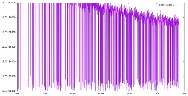
It looks to be between 16.0323 and 16.0324, with the upper bound coming down faster than the lower bound is going up, so I reckon it's closer to 16.0323.
Update: it is between 16.03231 and 16.03238. If I discard the first 30 results then it is between 16.03225 and 16.03232. So I reckon it is between 16.03231 and 16.03232, and the error on this range is only 10 seconds in 6 months.
If this is true, then the errors over 6 months for several possible trains are as follows:
As you go down the list the error reduces, but the maximum number of teeth increases.
It is tempting to try to go for 1:25 6:57 11:65 because:
It would mean making a new second wheel with 57 instead of 45 teeth, a new second wheel pinion with 11 instead of 6 teeth, and a new third wheel with 65 instead of 45 teeth.
Let's mock this up in CAD using involute gears of such module as meets the existing diameter, and judge what it looks like. I'll probably have to make custom tooth forms, but this will be a good start.
Looks like this:
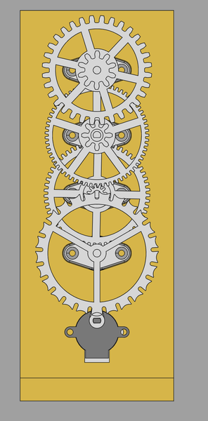
Doesn't seem outside the realms of possibility. The second pinion and third wheel are module 1.01, which is getting small, but I could definitely print it with a 0.25mm nozzle and just take a long time. Probably the dodgiest part is making the second wheel mesh with the first pinion, in CAD the first pinion is module 1.5 and the second wheel is module 1.17, which doesn't look like it will work. Will need a custom tooth profile on the second wheel, or maybe a new first pinion after all. But I think there is light at the end of the tunnel.
< 2023-12-03 2023-12-06 >