Last modified: 2023-11-10 21:46:38
< 2023-11-08 2023-11-11 >I asked on reddit about how to get a 90-degree phase shift in AC to drive my stepper motor. One person told me you need to use a microcontroller, which means they totally missed the point. But two people told me you can use just a capacitor to shift the phase. Is that right??
I tried it out in the Falstad circuit simulator:
https://www.falstad.com/circuit/
The resistor represents the load, and you can see the two voltage plots at the bottom. By playing around with the capacitance value I was able to shift the phase, but it seems like the more the phase shifts, the lower the amplitude gets.
However in my application I think this is completely fine! So next things to try are:
I wonder if the centres of the coils being tied together will be a help or a hindrance? Maybe need to try just driving "half" of each coil, and letting the common wire be common.
This video has an example of a clock made according to Harrison's principles: https://www.youtube.com/watch?v=N-wm39a6r_k
The guy in the video (Hefetrueb?) recommends the book Harrison by Jonathan Betts which I've ordered, as well as Perfecting the Harrison twin-pivot Grasshopper escapement by David Heskin available as PDF.
He also recommends "John Harrison's Contrivance" by Stuart Harrison, which I have also bought off Amazon but it was a listing with no picture and no description so I'm not sure what's going to turn up.
He also recommends Harrison Decoded by Rory McEvoy however this one is much more expensive so I haven't bought it. Although he does say it is "priceless" so maybe I should.
Hefetrueb used plywood for most of the clock but lignum vitae for "bearings and rotating rollers of lantern pinions".
He uses "beryllium bronze or beryllium copper" for pendulum spring, arbor pivots, and "knife edges of the anchor". Apparently it is very easy to work (make it red hot and quench it and it gets soft), and also very easy to harden (temper to 300 deg. C and soak for 3 hours and it becomes "so hard you can cut glass with it"). But highly toxic dust.
The pendulum has a "temperature compensation mechanism" that looks like weights that stick out to either side. The main pendulum rod is steel, but it has brass rods rising back up to some pivoted weights, and when the brass expands relative to the steel, it pushes the weights up which countracts the expansion of the pendulum.
Although it seems to me that the expansion of the brass actually pushes the weights down, which will make the expansion of the pendulum even worse. Is this an error in the design or have I misunderstood? He says "...the brass balls are lowered, and by lowering the centre of gravity of the pendulum, they accelerate the oscillation in fact". Which sounds wrong? But he says "because I flipped it from the bottom to the top, the effect is also inverted". So he has definitely thought about it, but I still don't see how it can be right.
He uses an automated winding system with an electric motor switched on/off by reed switches as the weight falls/rises.
An "agate plate with a v-groove" is used as a bearing for the anchor.
The anti-friction wheels have lignum vitae hubs running on beryllium bronze shafts.
The great wheel (?) has a beryllium bronze shaft and runs in lignum vitae bushes.
I think Hefetrueb might not be his real name as it says "Moritz Gretzschel" on the dial.
OK, I'm going to try out using the 6v transformer, and putting a capacitor in series with the supply to the second coil, with one side of each coil's supply via the red wire, i.e. common. I'll connect up multimeter probes to ensure that I'm getting a decent phase shift & decent voltage on each coil.
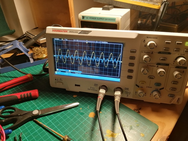
Here's what I'm seeing, with pink and red directly connected, and yellow connected to pink via one of the ceramic capacitors marked "104Z". The waveform looks pretty good actually! But the motor doesn't turn, just sits still, or vibrates if poked.
Oh, that's only 100mV/div on the second coil. If I recall correctly from playing in the simulator, that means the capacitance is too high. Try a smaller capacitor.
Next up: marked "103".
That's now at 5V/div on both channels. The motor just vibrates and does not turn. Obviously still too much capacitance.
I can't obviously see any "102" so I'm going straight to "101" now.
Looks broadly the same as "103". I'll try swapping pink for orange just in case. No difference.
I'll try a capacitor marked "15". Seems the same. I'm going to try two "104Z"'s in parallel. No difference.
OK, here's another idea: forget the capacitors. We power both coils through a diode, each coil only gets either the positive or the negative half of the waveform. Would that work? I don't know. Let's see what happens.
Looks like you'd expect:
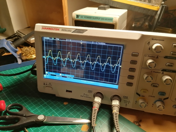
But it doesn't rotate, seems locked in place. This is with one diode connected to orange and one to yellow. I'll try swapping orange for pink... same thing.
OK, next idea. Try connecting an electromagnet in series with one of the coils to present an inductive load.
I think this is getting closer. It vibrates back and forth a bit but is definitely biased to one direction.
Try the larger electromagnet. Better!
Maybe try using the other transformer as an inductive load. Not as good. What about 2 of these in series? Even worse, surprisingly. Maybe too much resistance now, so it's like only one coil of the stepper motor is connected.
What about using the solenoid from the electronic safe as an inductive load? No good, doesn't help at all.
What if I leave the solenoid in line with the second coil of the stepper motor, but go back up to the 12v transformer? This works great! Runs at the right speed (as far as I can tell) and won't run backwards.
However, looking on the oscilloscope, it looks to be almost perfectly in phase and just slightly lower amplitude. Maybe try the "104Z" capacitor but with the 12v transformer?
No, does nothing, now it will run backwards again. So why did the solenoid help?
I switched the capacitor to the big electromagnet, this is the waveform:
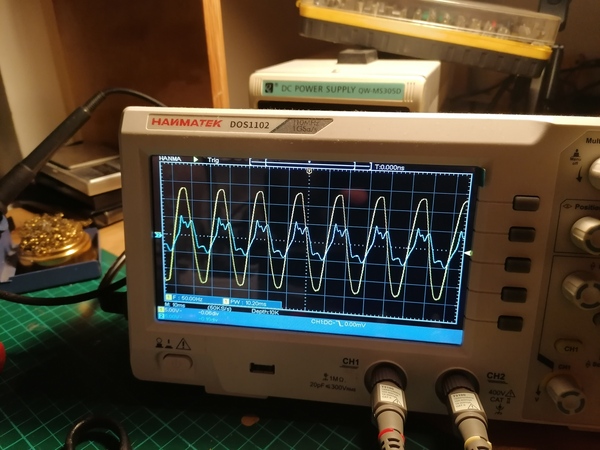
You can see it is slightly phase-shafted. And it works very well, the motor won't run backwards and runs at a constant speed, so it does what I want. But it seems like quite a blunt instrument, I don't know why it works and I don't know how to get something simpler to do the same thing, and it's not a very clean sine wave.
Is it stopping the motor from getting so hot? Not clear. I don't see why it would (if anything it should get hotter as there is more current going through it, no?).
I've set it to the correct time and will leave it running like this for a while. Interesting things to find out are: