Last modified: 2023-10-01 19:57:11
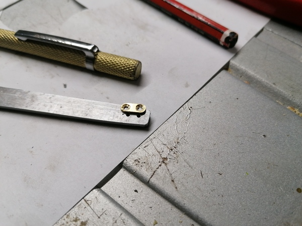
< 2023-09-30 2023-10-02 >First job was putting the M1.6 threaded holes in the leg of the gauge, and making a clamping piece.
I made this clamping piece by hand:
I'm pretty sure I marked the holes in the brass piece more accurately than this, so the drill must have wandered. Still, good practice at filing very small parts.
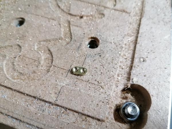
Next I'll try making it on the CNC router...
Much better:
So next up is making up artwork for a scale. I think I want to take a bunch of measurements of the jaws open to different sizes, and the corresponding distance between the pointer and the brass clamp, and then set up those reference marks in Inkscape or similar, and interpolate all the other marks. The marks can't all be spaced equally because we're really measuring the chord length, rather than the arc length, at the jaws.
But before that, the handmade jaw probably wants filing to a better shape. Actually maybe both parts want some more "finishing" now, so that I don't take the scale out of calibration later.
All cleaned up:
I used hand files, 320 grit wet-and-dry paper, and a little wire wheel in the Dremel tool. The wire wheel works quite well, if you move it slowly it can take off tiny amounts of material in a nice controlled manner, and leaves a matt finish. Wear goggles though because it shoots off tiny wires.
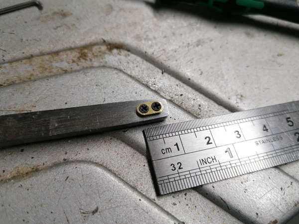
Radius from pivot to tip of pointer: 118 mm
Matching spot on other leg is in between the "top" screw hole and the erroneous centrepunch.
| Jaw opening (mm) | Scale distance (mm) |
|------------------|---------------------|
|                0 | 70                  |
|                1 | 64.3                |
|                2 | 59.7                |
|                5 | 45                  |
|               10 | 20                  |
|               13 |  4.7                |
So I'm saying that the scaledistance = 70 - 5 * jawopening. I think the readings that are a bit
different from this are because of the shape of the jaws? Or measurement error? Let's draw up a
first scale and try it out.
Measuring the distance from the pivot to the jaws gets me about 23.4 mm, but 118 / 5 = 23.6 mm,
so maybe that is the discrepancy? Maybe instead of a factor of 5, it should be 118 / 23.4 = 5.04?
Yeah let's go with 5.04 for the first attempt. Now the question is: Inkscape or LibreCAD? Let's try out LibreCAD, and revert to Inkscape if I can't do it.
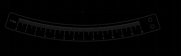
I didn't have any trouble labelling 0.25mm graduations by hand in pencil:
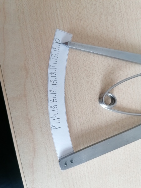
Although I could have done with a bit more space to write the numbers. The spring stops the jaws from opening any further than about 11mm, but I reckon it's worth labelling the scale all the way to 13mm, because in a pinch the spring can be removed to measure larger things.
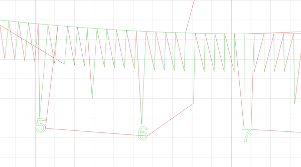
Well I went to the trouble of drawing this up in LibreCAD:
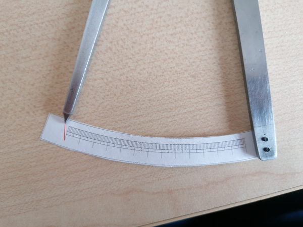
But, oops, the scale doesn't line up! I erroneously made the spacing at the bottom of the large graduations line up, instead of the top where the pointer is, which means it is wrong. The red line shows the point that has the correct linear distance from the right-hand edge. So basically the scale is drawn with the wrong radius.
It was extremely laborious to draw this in LibreCAD so I really don't want to have to do it again. I'll do it with the "polar array" features this time, as the spacing looks almost exactly the same anyway.
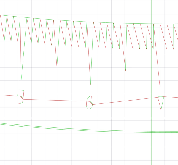
OK good, this time the scale is satisfactory:
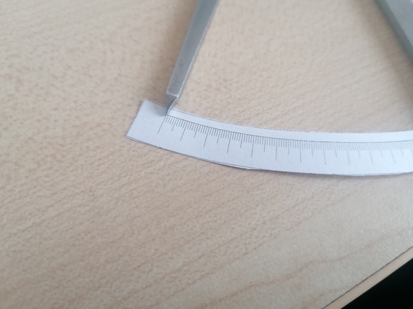
But, errrr, it's not concentric with the material it's on:
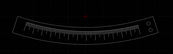
I'm just going to leave the mounting holes and the scale in place, and draw a new outline.
OK, ready to make this I think:
Can LibreCAD do CAM for me? I only need an engraving path and an outline path. Probably I should move the engraving to a separate layer.
Trying to import douzieme-scale.dxf into FreeCAD reliably segfaults it - I should maybe investigate.
Reported on github: https://github.com/FreeCAD/FreeCAD/issues/10882
Despite the homepage saying "LibreCAD started as a project to build CAM capabilities into the community version of QCad", it seems it still doesn't have any CAM capabilities. So I really need to find a tool that can do CAM from a DXF file, or else re-make the outline in FreeCAD, and import the engraving into Inkscape.
dxf2gcode looks like it's meant to be able to do what I want, but it also crashes when trying to load my DXF.
I managed to import the DXF into FreeCAD by:
Finish up the scale:
~/cad/watch/douzieme-engrave.gcode)~/cad/watch/douzieme-profile.gcode)To open it Inkscape I have to open with scale = 25.4 / 96 = 0.264583. I don't quite understand why, something to do with inches and dots-per-inch. I kind of get dpi, but where are inches coming from?
Hmm, it looks like the text engraving is not going to do what I want:
I think I need to get LibreCAD to export the text as a path instead of an "MText". Use the "Explode" tool in LibreCAD for this. Sorted:
Also tomorrow:
For the next metal escapement model, I am tempted to try to do at 1x scale. The only obvious stumbling block is that the radius at the root of the escape wheel teeth is 0.3mm, which is too small for the 1mm cutter. So I propose starting with an oversized disc, superglued down to some workholding platform. Then do the majority of the machining using the 2mm end mill, then just cut a bit deeper into the roots with the 1mm end mill, and then try using one of those weird serrated fibreglass-cutting tools to bring the roots to their final size.
Those tools probably won't work very well on metal, but they don't have to do a lot of work so it might be fine. Worth a try anyway.
< 2023-09-30 2023-10-02 >