Last modified: 2023-09-21 03:52:21
< 2023-09-19 2023-09-21 >Status on debugging the lever escapement was:
So I'm going to actually screw the old frame together, and put some pressure on the lever to stop it swinging freely, and video it as the escape wheel moves, to work out what angle it is moving through.
It should be 12 degrees according to CAD, but on the new frame it is only 5 degrees. What is it on the old frame?
I think it's down to the friction of the pivots. When I applied pressure to the lever's shaft on the old frame, it started oscillating by only a tiny amount.
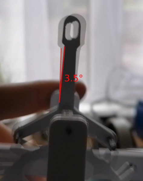
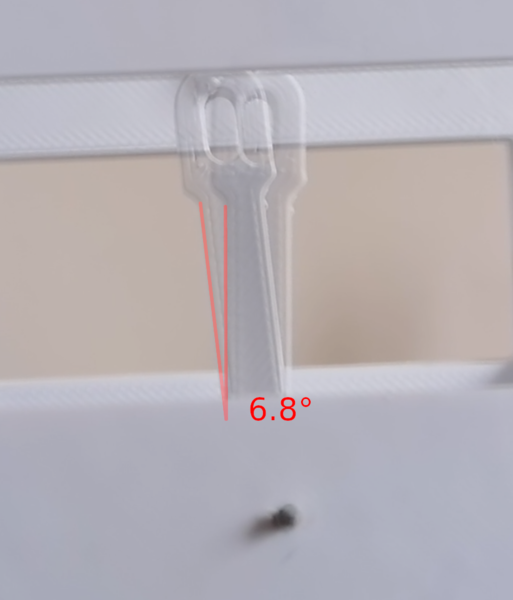
I did video the test configuration, and found:
Only 3.5 degrees! So it is actually even worse in that example than it was on the new frame.
With my finger removed:
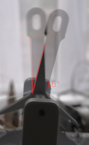
So the only reason it was working well without the lever is because the pivots had such low friction, allowing the inertia to carry the pallets further than is actually necessary.
So the sticky pivot holes in the new frame do highlight an actual geometric problem in the escapement. The lever should need to move by 12 degrees to allow the teeth to escape, but empirically only 3.5 degrees on the old frame, and 5 degrees on the new frame, is sufficient.
Why is this different to CAD? Possibly because of the radius on the end of the escape wheel teeth.
I tried to measure the end of the teeth with the Vernier caliper, and it looks like the diameter is 1.2mm, so a 0.6mm radius. This is quite reasonable given that the 3d printer nozzle is 0.6mm.
Here it is under the microscope, next to a piece of stainless steel wire measured at 1.6mm:
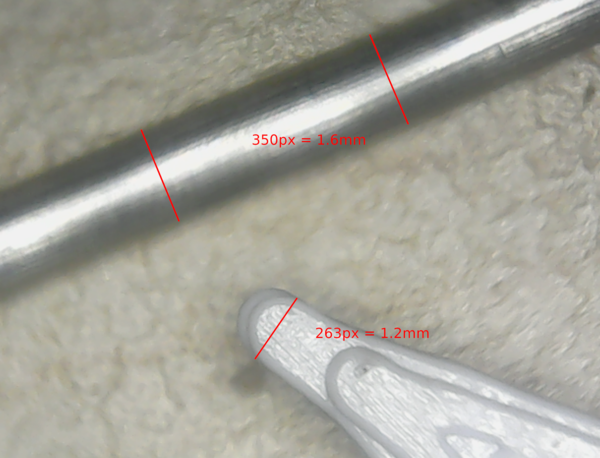
A 0.6mm radius indeed.
I'll also measure the outer diameter of the escape wheel: 76.3 mm
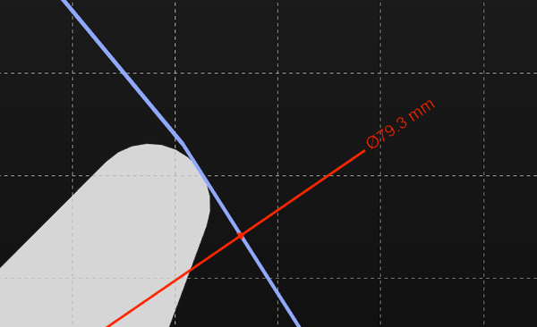
In CAD, we have no radius whatsoever on the end of the tooth, and the diameter is: 79.3 mm
So our real-life escape wheel is a good 3mm smaller than it should be, just because of the radius on the end.
So let's re-design the escape wheel so that it ends up at 79.3mm with a radius on the end, print that, and see how we go...
First impression is it feels much better, but...
That's not much better than 5 degrees! I wonder if I made an error in measuring it. It does run much better than before.
https://www.youtube.com/watch?v=1olZRxL97JM
I think the intermittent clonking noise is caused by the weight on the right-hand side of the balance wheel hitting the cable tie that is holding the hairspring. It seems to be in phase with the rotation of the escape wheel, so possibly some part of the escape wheel provides slightly more impulse.
I don't know why it's out of beat. It could be because the spring is pulling the balance wheel to one side, or the balance wheel is not balanced correctly, or because the pallet interactions are not symmetrical.
I changed the hooks that hold the nuts so that I could measure isochronicity...
4 nuts: 1.9 to 2.0 Hz
6 nuts: 2.1 Hz
8 nuts: 2.3 Hz
So doubling the weight increased tick rate by about 15%. On 2023-09-12, we had a configuration with the non-lever version of the escapement where doubling the weight increased the tick rate by 10%. So it doesn't appear that the addition of the lever improves isochronicity. There is still the confounder that the new frame provides more friction, however.
What if we make the hairspring stronger? Needs more weight to run.
6 nuts: 2.96 to 2.97 Hz
12 nuts: 2.99 to 3.05 Hz
So even if we take the most extreme values of the ranges, doubling the weight only increased the tick rate by 3%.
But is it really the hairspring that helped, or just the extra weight? How does 6 nuts vs 12 nuts compare if we have the weaker hairspring?
6 nuts: 2.1 Hz
12 nuts: 2.3 Hz
Interesting! Still an increase of about 10% for a doubling of the drive weight. So, yes, the stronger hairspring is definitely helpful.
https://github.com/prusa3d/Prusa-Firmware-Buddy/releases/tag/v5.1.0-alpha1
Prusa have released an alpha of a firmware update for the Mini that provides "input shaping" that should simultaneously give higher quality prints and faster printing.
According to the comments on this video: https://www.youtube.com/watch?v=klR189VP59U it is about 2-3x faster for the same quality, big if true.
My new escape wheel is a 38-minute print with these settings:
You need to use a new PrusaSlicer to get profiles for the input shaping, let's download it and see what it says for printing speed...
Boooo, it only has input shaping profiles for a 0.4mm nozzle. It comes out as a 43-minute print with these settings:
So it's 13% worse print speed, but with 33% finer layer height and 33% finer nozzle. Possibly worth it, unclear. I'll probably wait until the profile for the 0.6mm nozzle is available.
We got some more bits of plasterboard up:
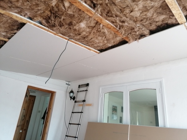
We're cutting them small so they're not as heavy to lift, and we are doing an exceptionally poor job of this, but the camera is very kind. Fitting this plasterboard is the worst part of the process so far.
It's too wet to do any siliconing.
Some blog posts I want to write:
I think it would be cool to put a mark on the winding ring lined up with the stopwork thing on the outer barrel, and line up the hand with the stopwork thing on the inner barrel, so that you can look at how far the hand has to move to reach the mark, to find out how long the watch is going to run.
< 2023-09-19 2023-09-21 >