
CAD Dojo
02: Mains plug
Wed 5 February 2020
Background
An ubiquitous, but often-overlooked, everyday object is the humble mains electricity plug. In the UK, these must conform to British Standard 1363, although plenty of non-conforming plugs are also sold, of varying quality.
There are lots of different styles available, that have only minor differences to the outer shape, but they're all laid out the same inside. There are also varieties available which are moulded in a single piece over the top of the wires and can therefore not be disassembled. I will obviously be copying one of the "user-serviceable" plugs.
Goal
Create a CAD model for a mains plug compatible with UK mains sockets.
Also, 3D print it and see if it works. Unlike the lathe tool holder, this might actually be a viable part.
Design
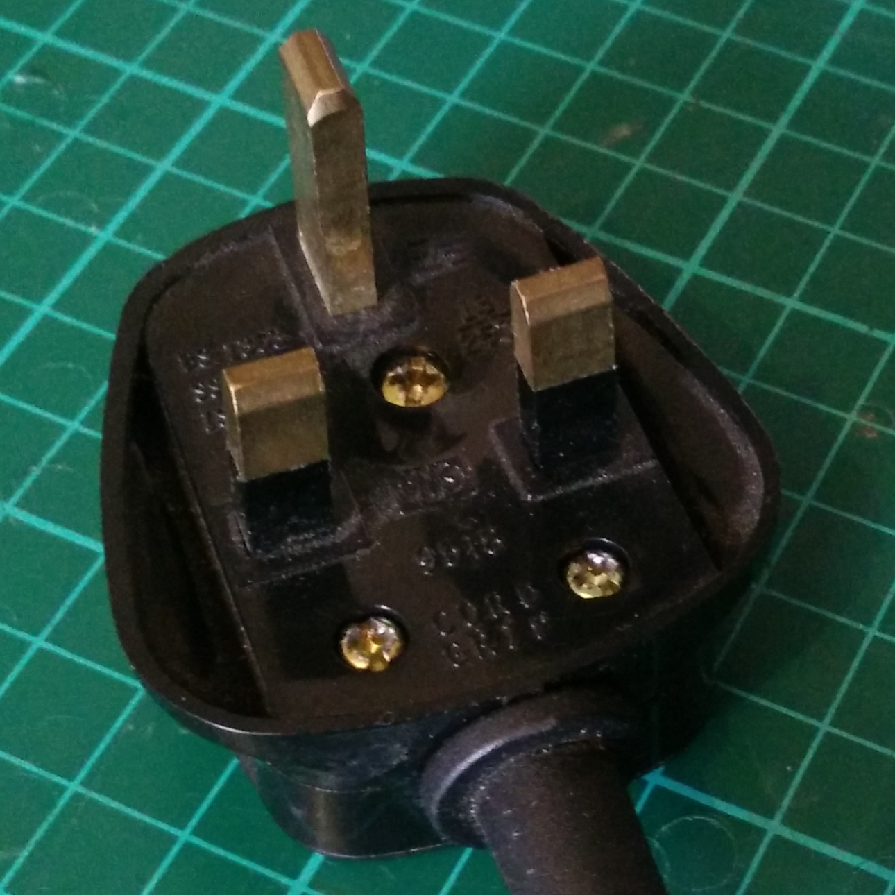
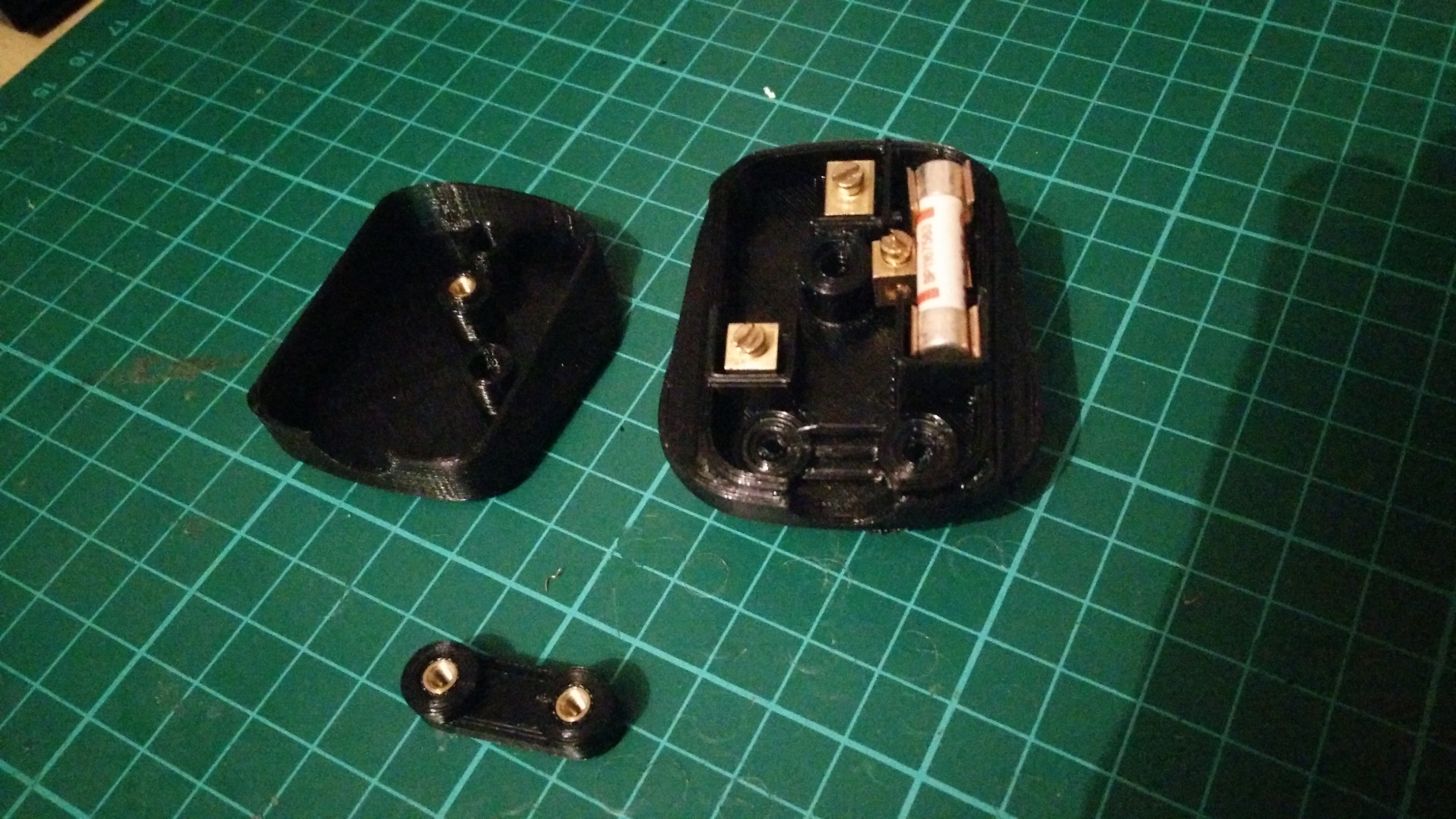
I started by dismantling an existing plug to copy the dimensions.

I was surprised to find that the earth pin was not connected to anything, because it is the plug for an anglepoise lamp made almost entirely out of metals. I bought the lamp secondhand, and I think it is likely that originally it did have an earth wire, but at some point somebody has put a new cable on it and didn't bother getting an earthed one. Oh, well.

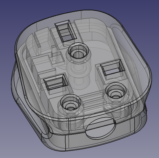
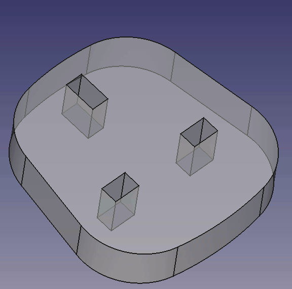
The key parts of the plug are the two halves of the case, three pins, fuse, fuse holder, cord grip, cable, and screws. Due to my affinity for 3D printing, I only CAD'd the plastic parts, but now that I come to think of it it might have been a good idea to CAD the metal parts as well.
I used a Vernier caliper to copy the important dimensions from the original plug. If you were designing a real plug to manufacture, you would probably want to consult the BS1363 specification instead of ripping off someone else's design.
I actually found modelling this to be quite challenging. There is quite a lot going on inside a UK mains plug to keep everything attached in the correct places. Very impressive to think that this sort of plug was first designed and manufactured before CAD even existed! In the olden days, they had to be designed by hand on paper, and then the moulds had to be machined by hand as well, before plastic parts could be injection-moulded. Sounds like a lot of work, I don't know why anyone bothered.
The important features of the plastic parts are the holes for the pins, "walls" around the pins to prevent shorts, walls around the fuse and fuse holder to keep them in the correct place, kinda-serrated ridges to grip the cable, indented sides to help a human to pull the plug out, and screw holes.
I deviated from the design of the original plug in a couple of places. Firstly I decided to use brass threaded inserts instead of screwing directly into plastic, so I adjusted the design to accommodate this. Secondly I placed some of the walls slightly differently for ease of modelling, where it wouldn't affect the function, and finally some of the curve geometry is different just because it's really hard to accurately measure that sort of thing.
In addition to the functional features, the original plug also has quite a lot of text markings on it, which I didn't bother copying. On the inside these mark the pins as "L", "E", and "N" for live, earth, and neutral. On the outside it has another copy of the pin labels, a company logo, a BS kitemark, and various other standards markings.
All 3 parts were quite straightforward to print. I simply printed each part with the largest flat face against the build plate. Slic3r seems to have misinterpreted something about the main piece though:
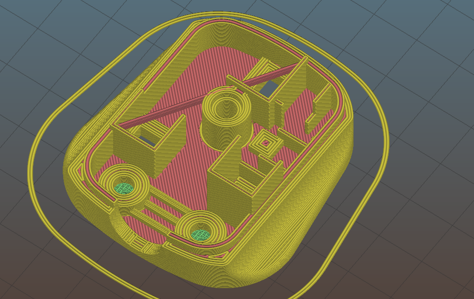
It has placed a long string of plastic right through the middle! I don't know what went wrong here, and didn't bother investigating too hard, I just cut it off after it had finished printing.
Having printed the parts, I fitted the brass threaded inserts by pressing them in using a soldering iron. I like these threaded inserts, they give a better quality look and feel compared to threading directly into plastic, or trying to trap an ordinary nut in the part somewhere. The soldering iron heats up the insert, which heats up the plastic and allows it to deform, then the insert easily slides into the hole, and as the plastic cools and shrinks, it grips the insert nice and strongly.
I pinched the pins, fuse, and fuse holder from the plug I took apart. The pins are a tight push fit in the rectangular holes. The fuse holder just sits on top of some of the walls, and is mostly held in place by the fuse, with the lid part preventing it from falling out.
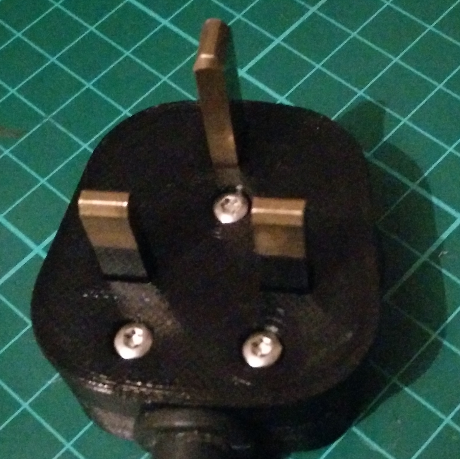
I then wired up the plug and screwed the lid on:

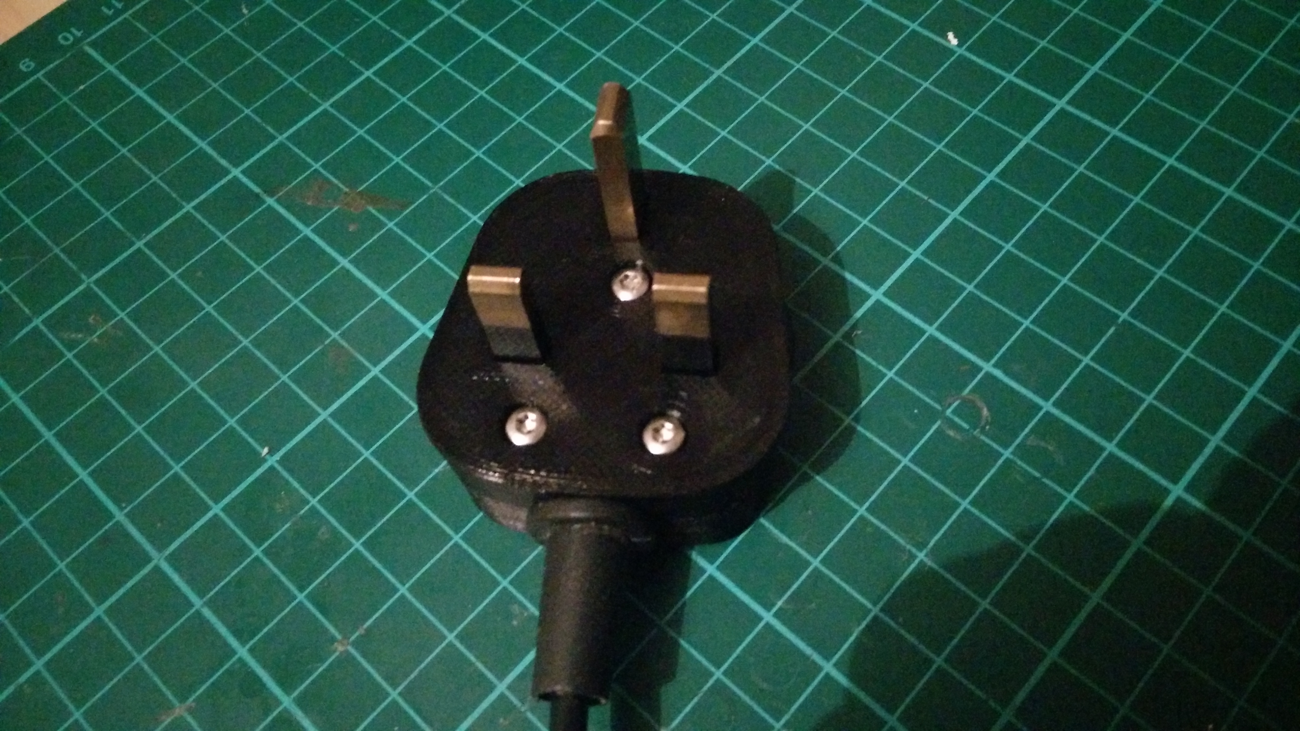
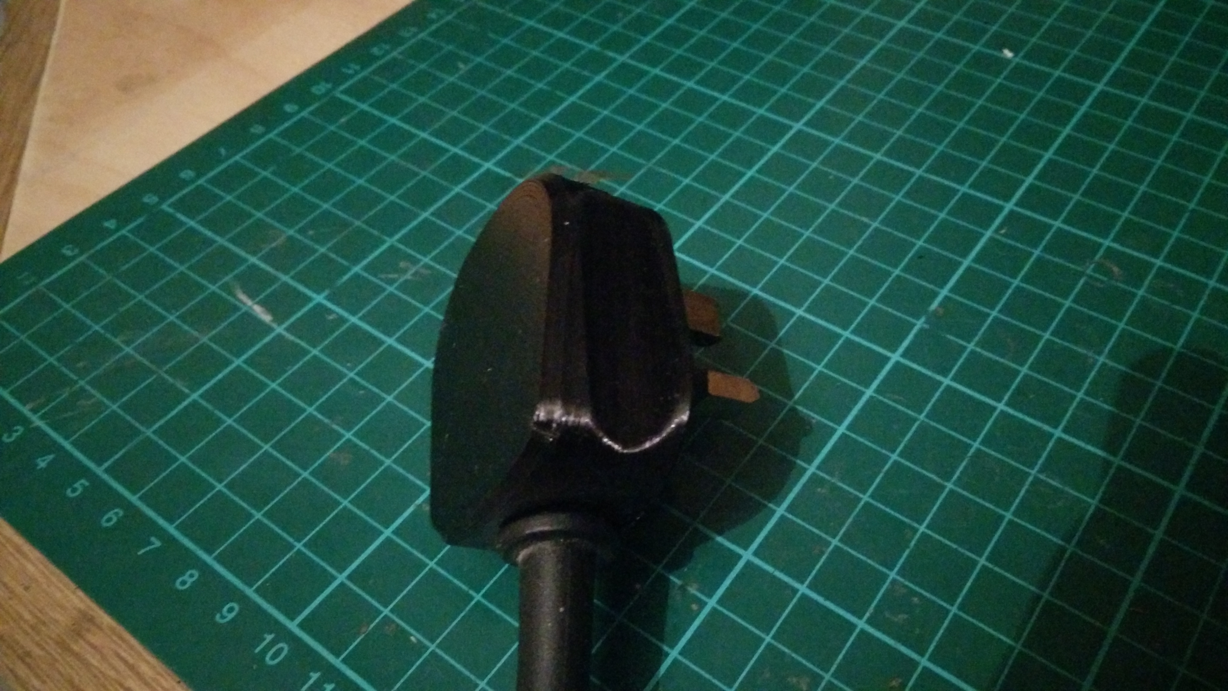
Apologies for the poor lighting in the photos. Normally I use the lamp to illuminate things, but obviously I can't turn the lamp on while I am taking pictures of the lamp's plug.
Evaluation
I plugged it in and found that the lamp worked, and I did not get immediately electrocuted, so that's a success on both fronts.
It is likely that my plug is not compliant with BS 1363. I haven't actually read the standard as the only place I could find it wanted me to buy a hard copy. But I suspect it mandates at least some of the text labelling that the original plug had, and it probably also insists on some sort of flame-retardant plastic being used, which my Taulman 910 almost certainly isn't. But it's good enough for me, and I think I'm going to leave it attached to my lamp cable as I quite like it.
Modelling these parts gave me a new appreciation for the design of the UK mains plug. I've wired plugs plenty of times before, so I've had enough opportunities to look inside, but I'd never really thought about what goes into the design of it. This is exactly the kind of thing I was hoping to get out of the CAD Dojo project, so although this one took me most of a day, I think it was time well spent.