
CAD Dojo
01: Lathe tool holder
Tue 4 February 2020
Background
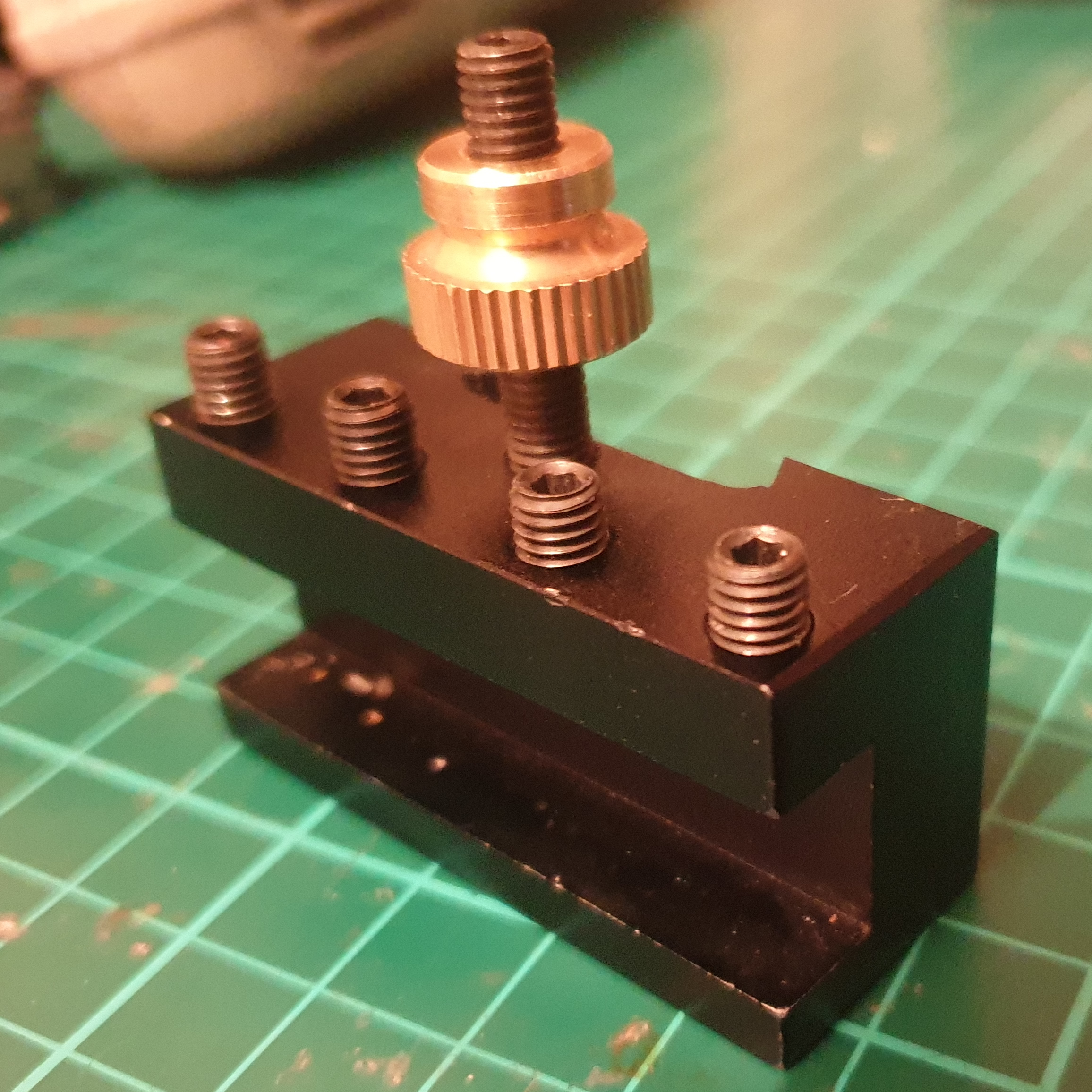
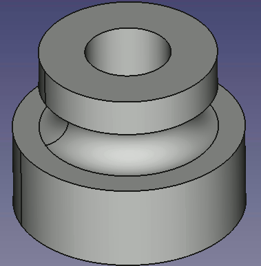
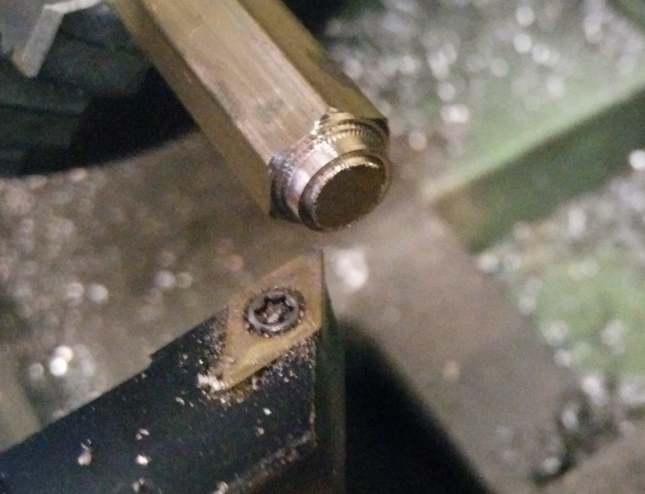
To facilitate quickly changing the tool on my lathe, I have a "quick-change tool post". Compared to the standard tool post, in which the tool is directly mounted on the tool post using 4 Allen screws, the quick-change tool post separates the tool holder from the post. The tool is held in the holder using 4 Allen screws, but the holder is held in the tool post using a cam that presses against the back of a dovetail fitting. To change the tool, you just loosen the cam, slide the tool holder off, slide a different tool holder on, and tighten the cam up again. The tool holder is machined out of aluminium.
There is also a knurled brass nut on a threaded rod. This nut rests on top of the tool post so that when the cam is tightened, the tool is at the correct height. To adjust the height, you loosen the cam, adjust the knurled nut, and then tighten the cam again.
Goal
Create a CAD model for a tool holder compatible with the mini lathe quick-change tool post.
I also plan to 3D print it, and try to use it. Obviously a 3D printed part isn't going to be as strong as an aluminium one, but CAD Dojo is really about CAD practice rather than useful end products anyway. If the end product works, that's just a bonus.
Design
I derived all of the dimensions by measuring the existing part using a Vernier caliper. The trickiest bit was the dovetail as this was hard to measure. I measured what I could and guessed at the rest until the angles looked about right. I don't think it's super critical that it's exactly correct. As long as the final part fits the machine, it's fine.
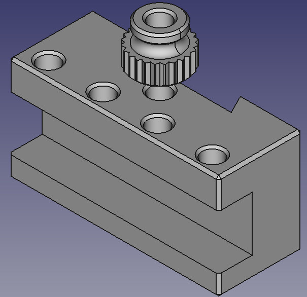
The tool holder was a pretty straightforward model to design. Start out with a pad made out of a rectangle with a dovetail, cut the slot for the tool, then cut out some holes for the M5 threads and chamfer some of the edges. I didn't model the threads because I'm still not good enough at FreeCAD to do this, and threads of this size are easy enough to cut by hand anyway.
I also modelled a copy of the brass part that is used to set the tool height. This was also pretty straightforward. Start out with a cross-section of the profile, revolve it around the centre line, cut out a single line for the knurling, use a polar pattern to copy the knurling all around the outside, and chamfer some of the edges. Chamfering the bottom edge can't be done with the Chamfer tool due to the knurling (it would chamfer along the edges of the knurl pattern instead of the bottom circumference), so I performed this chamfer using the "Groove" tool. I also added an extra chamfer above the rounded groove in order to reduce the steepness of the overhang, to help with 3D printing.
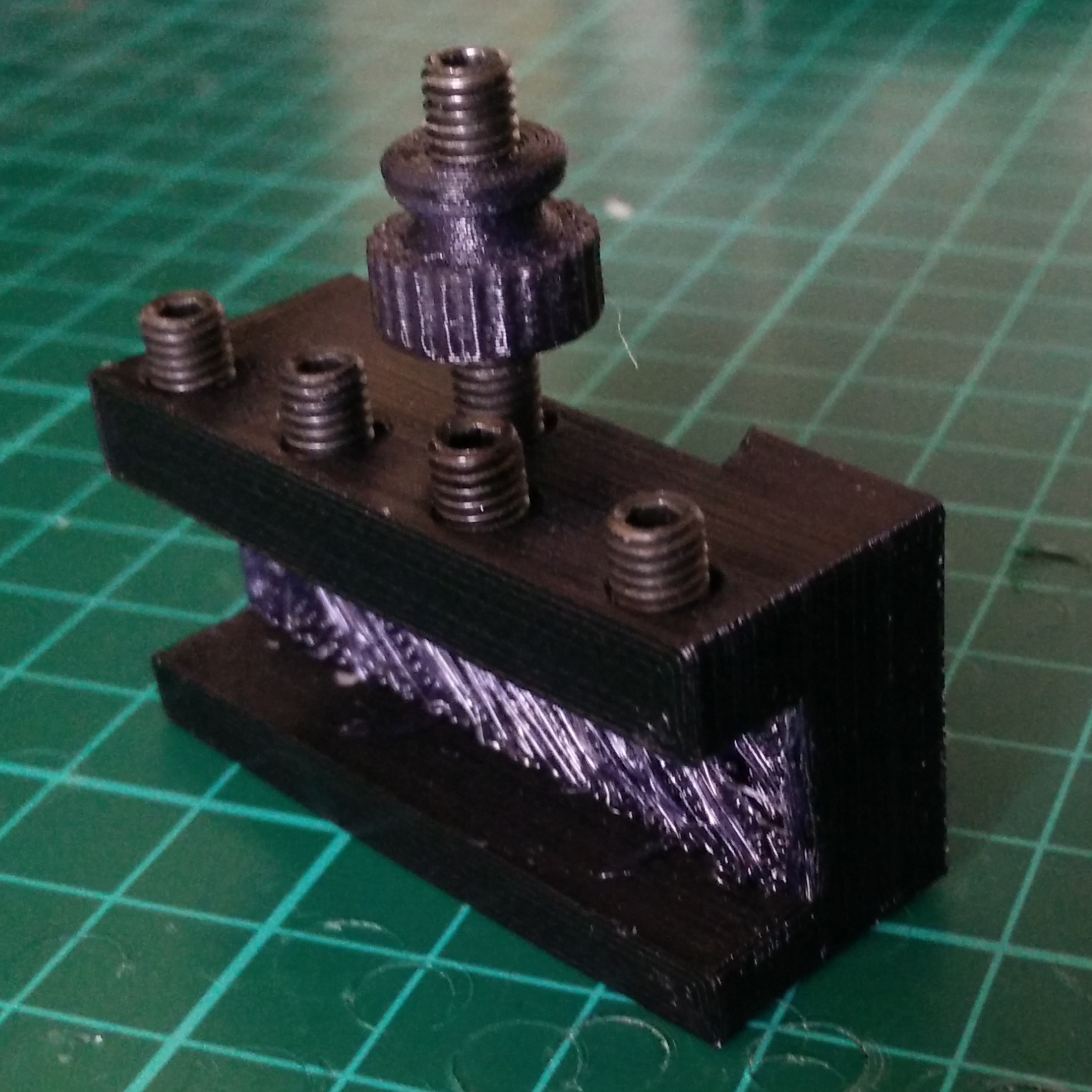
While the height adjuster is a very easy print, the tool holder presents a problem: there is no orientation in which it can be printed without creating a difficult overhang or bridge. That means we have to decide which of the potential overhangs we care about the least. I decided that the back of the inside of the slot for the tool was less critical than either the dovetail or the top/bottom of the tool slot, so I printed it with the dovetail facing upwards:
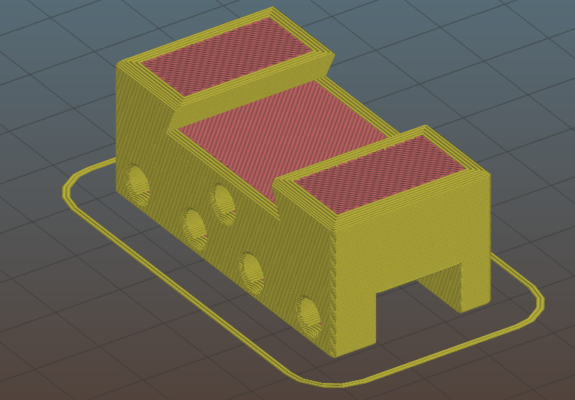
I printed both parts in Taulman 910 nylon, with no supports, 15% infill, 4 bottom layers, 4 perimeters, and 4 top layers, and I cut the threads by repeatedly running an M5 bolt in and out with a cordless drill until it freed up. (I don't have an M5 tap).
As you can see, the back of the slot that the tool sits in is very rough. Taulman 910 does not bridge very well. If I were to print another, I would enable bridge supports. Apart from that, it printed nicely.
Evaluation
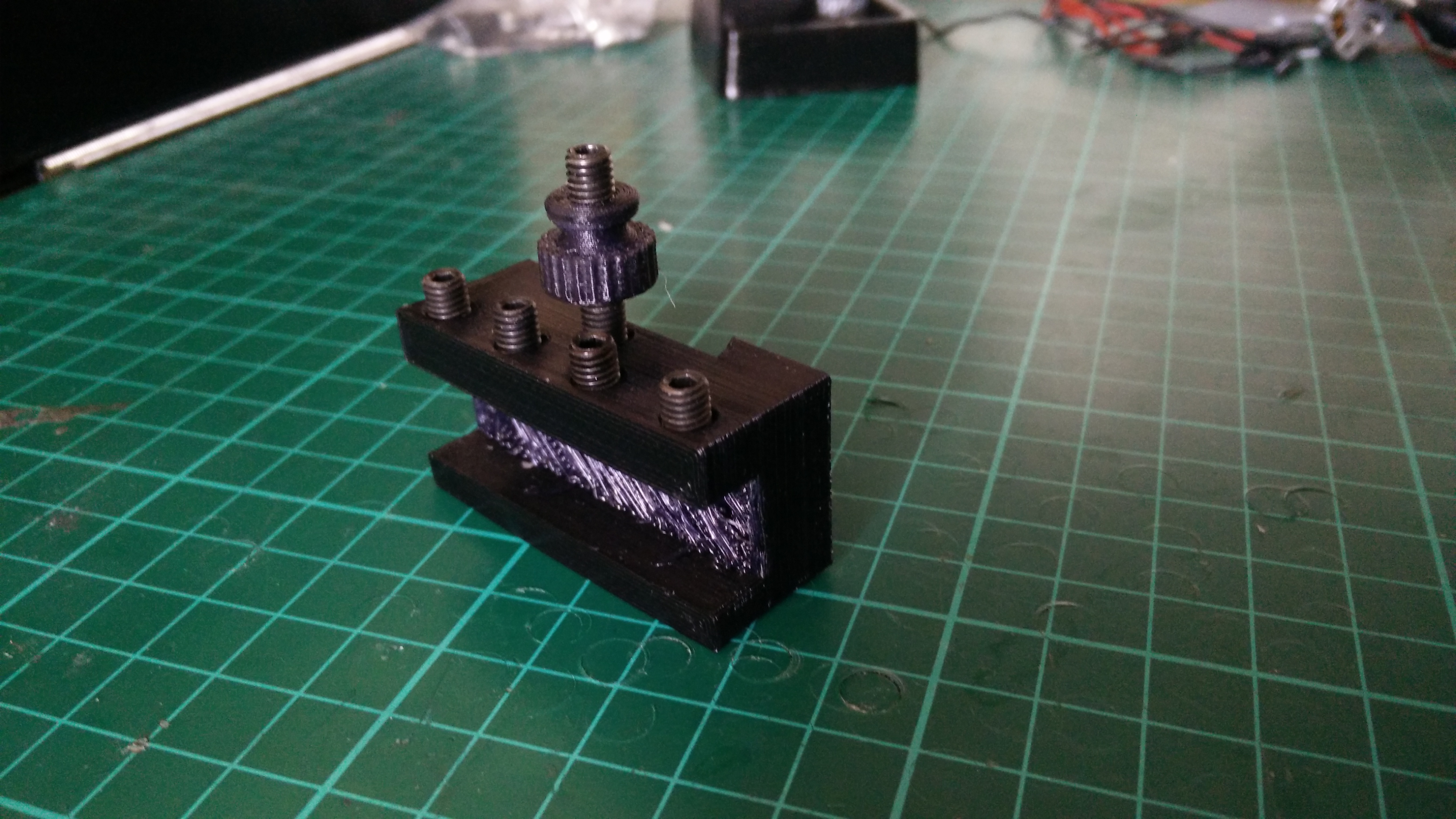
I mounted a tool in the slot and mounted the holder on the tool post:
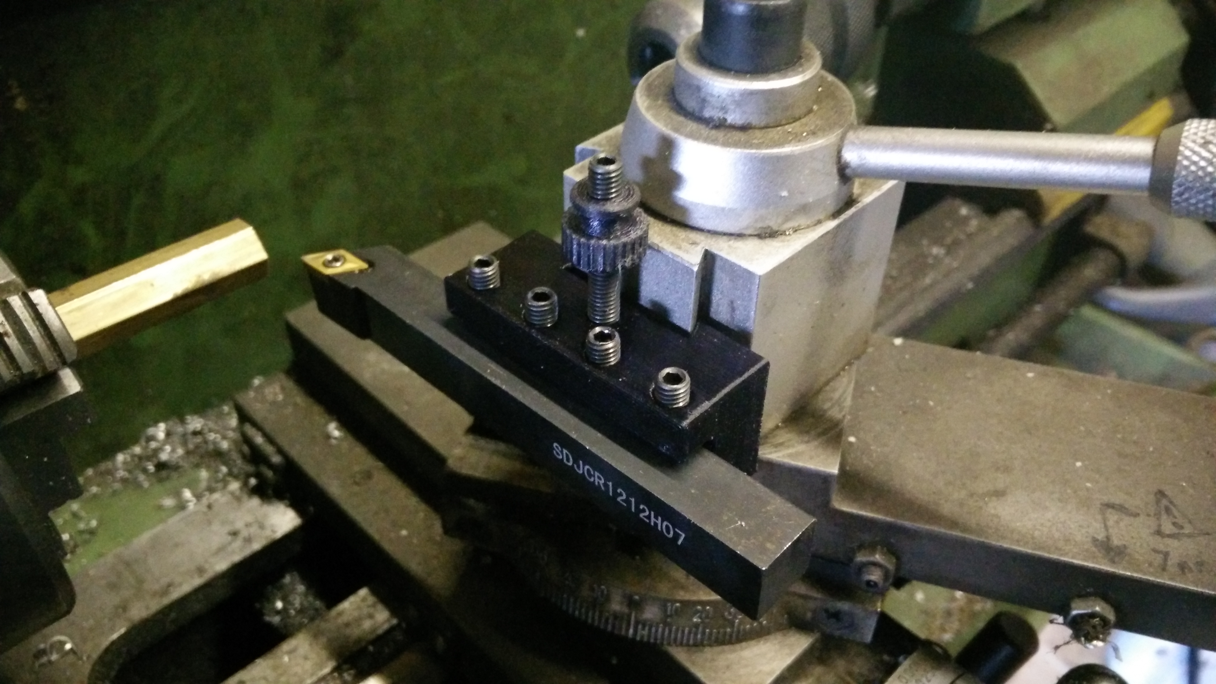
Everything fits, so the CAD model is perfectly good. It's an almost completely faithful reproduction of the original part, so in that respect it is a success.
Just to see what would happen, I tried cutting some brass. At first I took an extremely light cut and while it worked, it didn't feel very rigid. The tool was moving as it contacted the work and flexing around quite a lot. I don't think you could work to accurate dimensions this way. You can see how poorly it was cutting from the chatter on the surface finish:
Finally I stood to one side for safety, and pushed the tool hard into the work, to see which part would actually fail. Surprisingly, nothing violent happened. The tool was just gently pulled out of its slot:
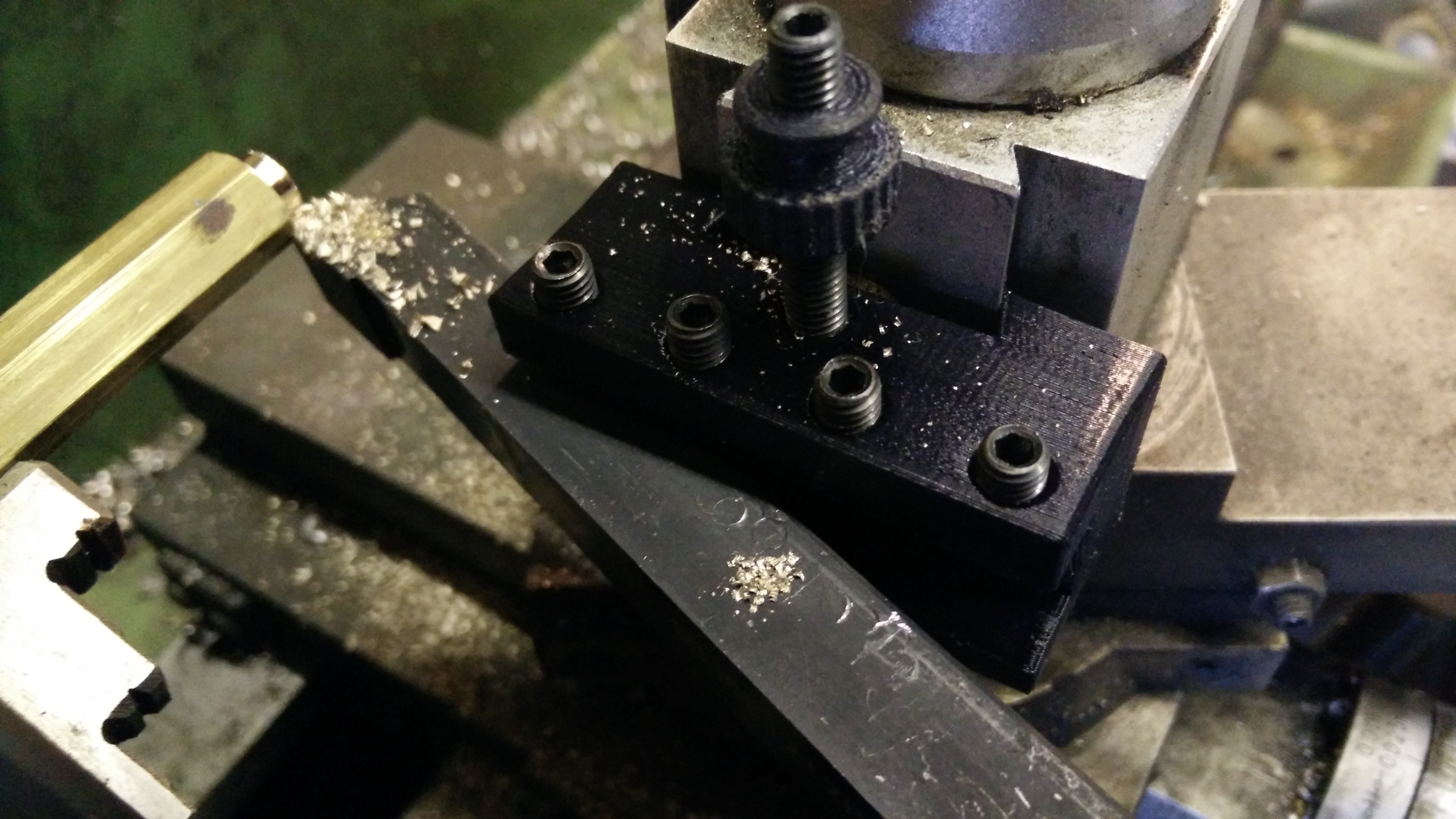
There is not very much clamping force available from a cantilevered bit of plastic. Tightening the screws further just caused the plastic to spread apart rather than the clamping force increasing, so it is impossible to tighten them enough for satisfactory tool-holding. The same problem is apparent in the dovetail. It is physically possible to rotate the cam further, but it just spreads the plastic apart rather than clamping any harder. It seems nylon is a poor choice of material for this part, and we would be better off with something much more rigid.