
SCAMP is alive
Sun 21 March 2021Tagged: cpu, electronics, software
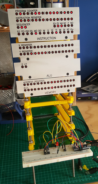
I have reached a good milestone on the SCAMP hardware: it can now execute code! It runs all the way through the test program correctly.
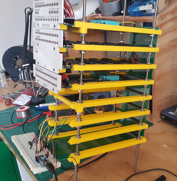
The card cage helps to hold the cards in place, and to avoid bending the pins when unplugging them. I also anticipate that it will simplify the construction of the case, because the case won't need to hold the rails. Unplugging the ALU is still pretty hard, because it is plugged into 120 pins.
I still haven't made a clock, so for now the CPU is being clocked by a short Arduino program. I've gone up as high as 10 Hz without observing any instability. I don't yet have any way to infer the state of the machine without looking at the LEDs, so if it went any faster than that I wouldn't even know whether it was working or not. Next steps are to make an adjustable 555 timer-based clock, and interface with the 8250 UART.
The test program just outputs the numbers 0 to 24 to the device at address 0. Each number is generated differently, and tests different things, starting off by just sticking the number in the x register and outputting that, followed by addition, subtraction, bitwise shift, bitwise logic, stack manipulation, unconditional jump, conditional jump, looping, relative jump, and function calls.
There is no actual device at address 0, so correct operation is verified by watching the lights. To output a value to device 0:
- the address register contains 0
- the bus contains the value
- the DI signal comes on, to tell the device to take input
Here's a video of SCAMP running the test program. If you pause the video every time DI comes on, you might be able to convince yourself that it is outputting the correct values:
(The button I have my finger on at the start is the "reset" button).
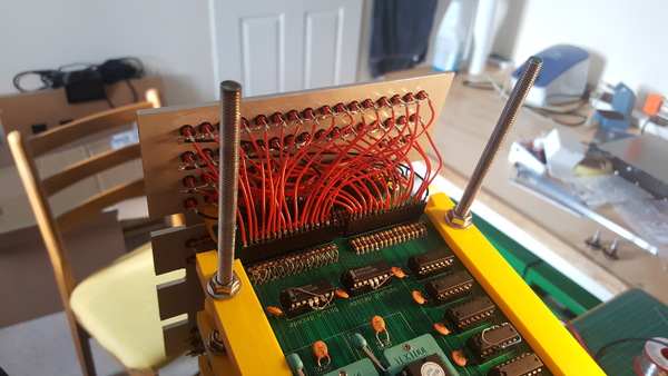
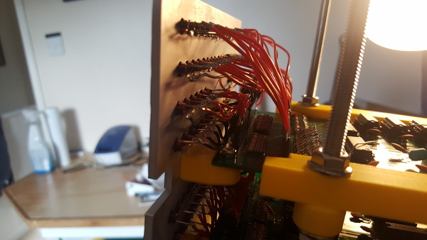
And here's a look at the wiring of the LEDs on the instruction card:
Bugs
Although I had already checked that everything would work at least 3 different ways (Verilog simulation, running on an FPGA, and the SCAMP emulator in C), there were still a lot of fun bugs to find and fix after I put the PCBs together.
Inverted "enable" pins on decoders
Two 74LS138 "3-to-8" decoders are used, each one decodes 3 bits of the microinstruction word into a selection of 8 possible input or output components for the bus.
(This design does mean it's not possible to output to 2 components simultaneously, but that's not something I want to do very often, and saving space in the microinstruction word was more important to me).
The 74xx138 has 3 "enable" pins. For it to apply an output, all 3 must be enabled. I had failed to notice that 2 of these enable inputs are active-low instead of active-high:
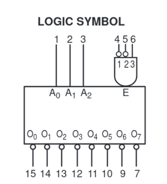
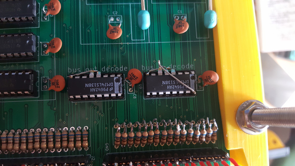
The "E1" and "E2" (pin 4 and 5) inputs have little circles to indicate that the signal is inverted, but I had connected these pins to VCC instead of GND, which means the decoders were never enabled. D'oh! My solution was to pop pins 4 and 5 out of the socket and solder a little wire to GND, and this worked.
bus_in conditional on not using the ALU
The "bus_out" decoding is slightly more complicated than "bus_in". One of the components that can output to the bus is the ALU, but the ALU also needs 6 more control signals to select its operation, which are all inapplicable when the ALU is not in use. For this reason, the bit that selects the ALU (EO) is separate from the "bus_out" bits, and the "bus_out" bits overlap with the ALU function selection:
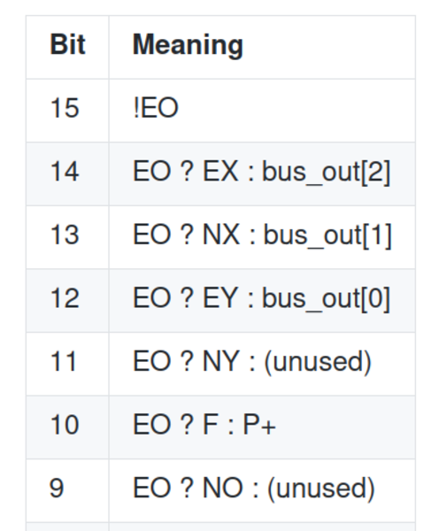
(See under "Decoding" in doc/UCODE.md).
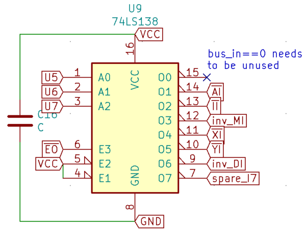
This means that for the "bus_out" decoder, one of the enable inputs needs to come from EO. So far so good. But when I designed the schematic, I copy and pasted the "bus_out" decoder to create the "bus_in" decoder, and forgot to remove the EO input from pin 6:
This means the output of the ALU can never be consumed, because when the ALU is outputting to the bus, nothing is inputting.
My solution was to pop pin 6 out of the socket, and connect it to VCC with a little wire (also visible in the above pic), and this worked.
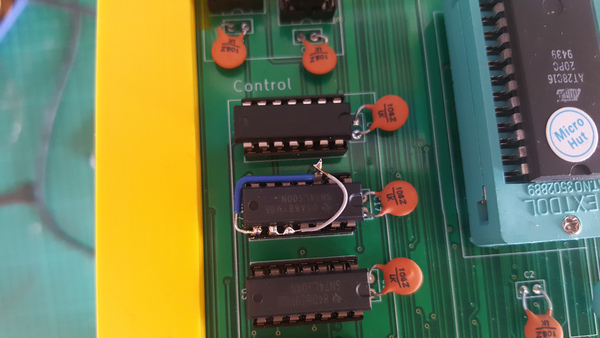
IOLH inverted
IOL and IOH ask for the lower 8 bits of the instruction word to be placed on the bus, with the upper 8 bits set to either 0 (for IOL) or 1 (for IOH). All of these signals are active-low, because the enable pins on the buffers are active-low.
For some reason, I decided that I could create IOLH by NAND of IOL and IOH (because, by De Morgan's Law, NAND is just OR but for active-low inputs), but obviously this gives an active-high output. I had a couple of spare NAND gates on the same chip, so my solution was to pop the IOLH output pin out of the socket, feed it into the 2 inputs to another NAND gate (grey wire) to use it as an inverter, and feed the output of that NAND gate into the IOLH pin in the socket (blue wire), and this worked.
I must have been tired or distracted when I designed the instruction card, as it has been the source of almost all of the mistakes!
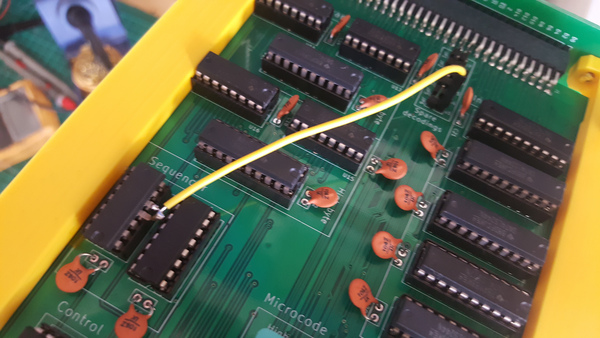
Sequencer reset glitch
So far, all of the mistakes have been simple logic errors, but the sequencer reset glitch was quite subtle, and I am pleased to have figured out what the problem was.
The first 24 or so instructions in the test program were executing correctly, but the 25th was only executing 3 of its 4 microcode steps. The problem was that the 3rd step used the ALU, and set the NY (negate Y) bit.
The sequencer counts up on every clock cycle. The upper 8 bits of the "micro-program counter" come from the instruction opcode, and the lower 3 bits come from the sequencer. Not all instructions take 8 cycles, so there is a signal RT (for "reset T-state") which is used to reset the sequencer to 0. This signal acts immediately, without waiting for a clock edge, so as soon as RT goes high, the sequencer resets to 0 which resets the "micro-program counter" to 0 for that cycle.
Since the combination of RT with any other control signals is meaningless (RT happens immediately, which precludes anything else), I thought it was quite wasteful to dedicate an entire bit of the microinstruction word to it. I encoded it in bit 11, which is shared with an ALU control signal: if the ALU is in use, bit 11 sets NY for the ALU. If the ALU is not in use, bit 11 sets RT.
The problem is that in real-life, signals don't all change simultaneously. If bit 11 ("NY or RT") comes high even fractionally before bit 15 ("I don't want to use the ALU") goes low, then we very briefly have a state where RT is set. This immediately resets the sequencer to 0, stopping the current instruction and moving to the fetch cycle of the next instruction.
That was pretty hard to figure out, but the fix was easy. I have some unused bits in the microinstruction word (I was thinking they might be useful for controlling something like a hardware stack pointer in the future), so I moved RT to one of the unused bits. Then I just needed to pop the sequencer's reset pin out of its socket and connect it to the new signal from the microcode.
I don't know why this problem didn't arise when running the CPU on the FPGA. Maybe I got lucky? Maybe there is some secret internal clocking going on in the FPGA that prevents the problem?
I think if I hadn't managed to work out what was going on here, I would have just disconnected the RT signal. The computer would work, just slower: every instruction would always take 8 clock cycles, even when it could be done in 3.
Next steps
I think the next thing I want to do is get the UART working on the breadboard. I think it should be straightforward, other than the fact that debugging anything without text output is inconvenient. At least getting the UART working will make everything else easier to debug.
Once I have the UART working I'll be able to start running the clock faster, and then I can think about building the "real" clock instead of using an Arduino. I think I'll want 4 clock sources selectable: manual clock with a switch, adjustable 555 clock with a potentiometer, fixed crystal oscillator, and an external clock input. The clock card would also have the reset button and probably a power switch.
And then finally I'll want to implement some sort of storage. The emulator currently provides a made-up block device that provides 1 byte per input instruction, and I know that this is borderline on being too slow to be acceptable. This leads me to rule out the idea of bit-banging SPI to an SD card, which leaves CompactFlash as the most likely storage medium. I'm not sure how much trouble I'll have interfacing with a CompactFlash card, I haven't found documentation to be particularly easy to find or understand. There are really only 2 primitives I need, though: read a 512-byte block and write a 512-byte block. Once I can handle those 2 primitives, we're done. I should then be able to stick my operating system on a CompactFlash card and boot it up for real!
Software
I've also made some progress on the software. Arguably more than on the hardware, but software is easier for me, so it doesn't feel like as much.
The system is usable but relatively slow, even with the emulator running about 20x faster than I expect the real hardware will. Mostly this is down to a combination of the slow block device interface, slow stack and bit-shift operations, bad code generation by my compiler, and code written by me without appropriate regard for how slow the CPU is.
But it works, which is good. A lot of the simpler Unix utilities are there (in a primitive form, at least): cat, echo, grep, head, ls, mkdir, more, mv, pwd, rm, stat, wc. There's an interactive shell with support for IO redirection and globs. It doesn't yet support pipelines because there's no multitasking, but I plan to hack that eventually by writing the output of one program to a file and providing the same file as input to the next.
There is also a compiler and assembler that runs inside the OS, although no peephole optimiser yet. There are a lot of bugs, but also a lot of it works. Here's an example session, showing a bit of command-line usage, and writing and running a program:
(Spot the deliberate mistake in the glob expansion!)
That session was recorded with the emulator running at maximum speed (so, about 20 MHz), and additionally with idle time of more than 5 seconds removed, mainly the compiler.
Compiling software is painfully slow. It takes over 1 minute to compile any program that includes stdio.sl. On real hardware that will take over 20 minutes, which is too slow to be tolerable, so I'll need to do something about it. I have several ideas for improvements but haven't yet done enough profiling to work out what's best, and getting new stuff working is currently more of a priority than getting it fast.
Writing a text editor is probably the next important step on the software side, so that I don't have to write code correctly, first-time, top-to-bottom, with cat. Obviously I don't really need an editor, because I always get the code right the first time and can easily write it in a straight line top-to-bottom...
The Build Your Own Text Editor tutorial walks you through the implementation of Salvatore Sanfilippo's kilo editor (so named because it is less than 1000 lines of C). Another potential source of inspiration is David Given's qe editor for CP/M, which uses an interesting gap buffer data structure to store the text.
If you like my blog, please consider subscribing to the RSS feed or the mailing list: