
CAD Dojo
03: Scraper
Wed 19 February 2020
Project
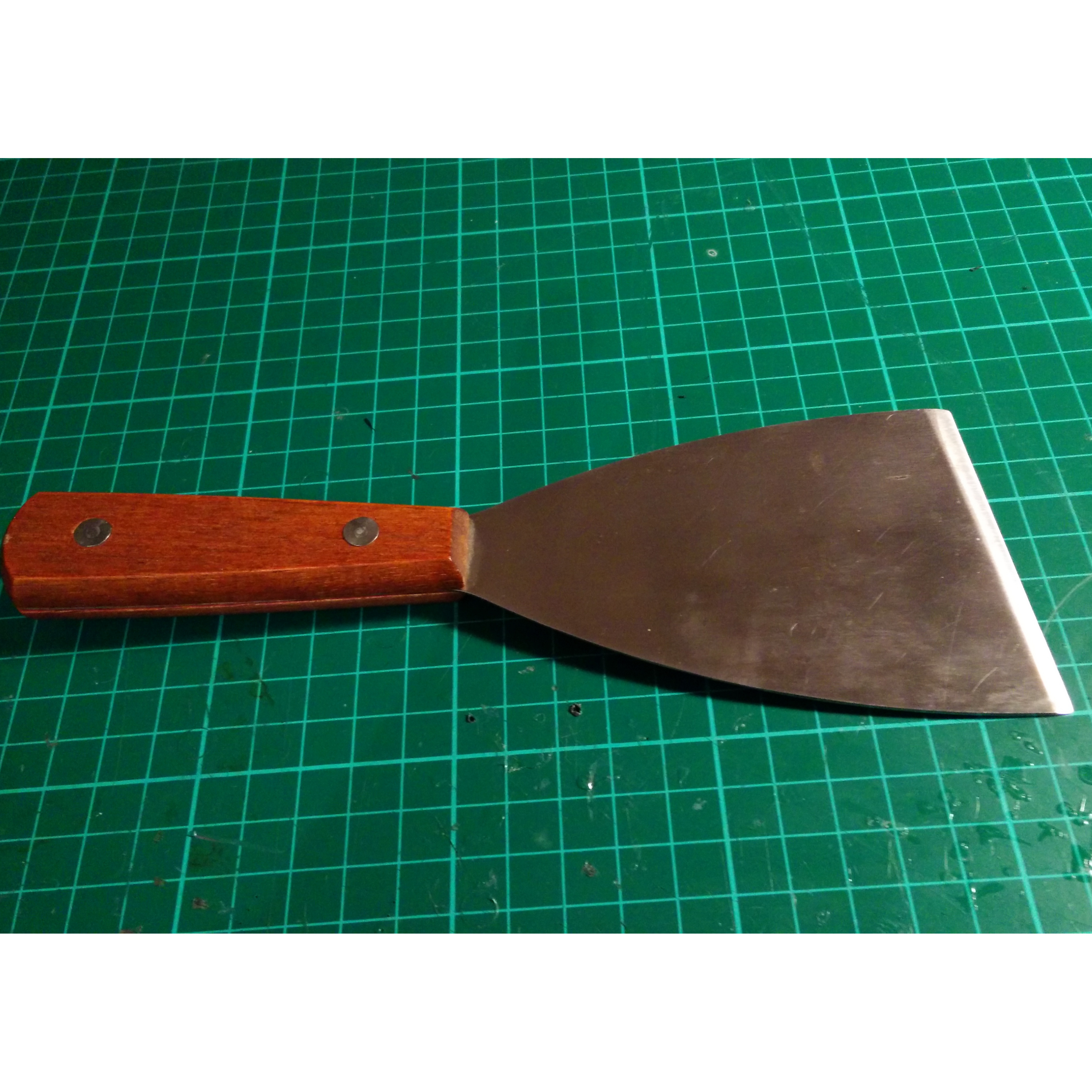
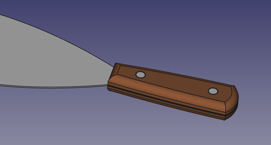
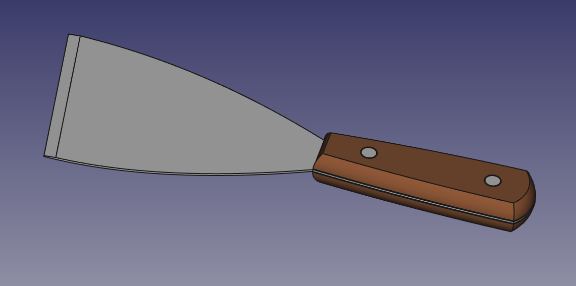
My 3D printer came with a scraper, which I use to remove prints from the bed when they're stuck too hard to remove by hand. It has a wooden handle made of 2 identical scales, and a slightly-sharpened blade, with the scales attached to the blade with 2 chunky rivets. Also the blade is wider at one side than the other, I'm not really sure why.
This CAD Dojo project is to create a CAD model of the scraper. I'm not going to 3D print it because there's not a lot of point. If I wanted to make one, I would 3D print the handle pieces, turn the rivets on the lathe, cut the blade out of a sheet of stainless steel using a paper template exported from the CAD model, and sharpen the blade with a file.
Design
Blade
I started by modelling the blade. The profile of it is quite straightforward. The handle shape is made out of 3 arc sections, the sides of the blade part are a pair of B-splines, and the front is a straight line segment connecting the B-splines. The tricky part comes when we want to add the bevel to the front of the blade. If the front of the blade was parallel to one of the base axes, we could just create a sketch on one of the base planes and cut a bevel straight across the width of the blade, but due to the funny angle, this isn't possible.
The solution I settled on was to create what I called a "bodge pad" on the end of the blade, whose sides provide a plane facing in the direction that we want to cut the bevel. The bodge pad is created as a sketch on the top flat surface of the blade, with lines parallel to the edge of the blade, and then padded straight upwards. The bevel is then cut out large enough that it completely removes the bodge pad, leaving behind a neatly-bevelled edge. Without the intermediate bodge pad, there would be no reference plane on which to create the sketch that cuts the bevel.
Possibly a FreeCAD expert would know how to create a datum plane using the edge of the blade as a normal axis, which could then be used as the sketch plane, but I couldn't work out how to do this.
Finally, 2 circles are cut into the blade to create holes for the rivets. These could alternatively have been incorporated into the sketch that created the initial pad, but I found it more natural to add them as a separate feature.
Rivets
The rivets are 2 simple cylinders, in separate bodies, centred on the rivet holes in the blade. They have to be in 2 separate bodies rather than 1 body that contains both rivets because a body must contain a single connected solid.
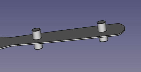
I used a shape binder to ensure that the cylinder for each rivet is centred on the corresponding hole in the blade piece. If the position of the holes in the blade is ever changed, the position of the rivets will automatically update to match. The rivets have a small chamfer on the ends just to help visually separate them from the handle scales.
Handle
I used another shape binder to copy the shape of the handle, and the rivet positions, into the handle body, and then pad it up to create one of the scales.
The tricky part here is adding the rounded edge to the handle. An easy cop-out would have been to add a filled to the top edge of the handle and argue that it's close enough, and indeed it would be a perfectly acceptable design for the handle:
But the point here is to get better at CAD, not to make life easy, so I had to learn how to use the "SubtractivePipe" tool. To do a SubtractivePipe, you must define the profile that is to be subtracted, and the path along which is to be piped. I created a new sketch to define the profile, it's just an arc section being removed from the outside of the handle. I defined the path using the bottom edges of the pad that creates the main shape of the handle.
There are quite a lot of options to fiddle with, but you can basically just try out different modes at random until it does the thing you wanted it to do. In my case I think the critical point was that I wanted the corner transition mode to be "right corner" rather than "transformed", because I want the direction of the swept sketch to steer around corners instead of always facing the same direction. While you adjust the settings, it gives a nice preview of the shape that is going to be subtracted.
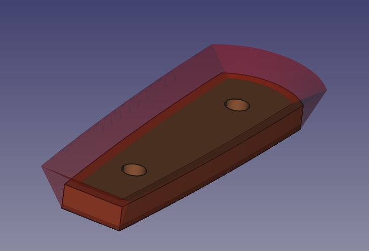
The reason that the top-left edge of the sketch sticks out at a funny angle (and therefore the subtracted pipe sticks out at a funny angle) is that I had some difficulty getting it to create a SubtractivePipe when the edge of the shape I wanted to subtract was exactly coincident with the shape I was subtracting from. Perhaps some numerical error had it thinking there were some microscopically-thin surfaces remaining that it didn't know how to handle, I'm not sure. Subtracting extra material from empty space seemed to solve it, at any rate.
Having created one of the scales, I used the "Part" workbench's "mirror part" tool to create a second copy that is mirrored across the x/y plane. This is still linked to the first part so that any changes made to the first scale are automatically reflected in the mirrored one.
Evaluation
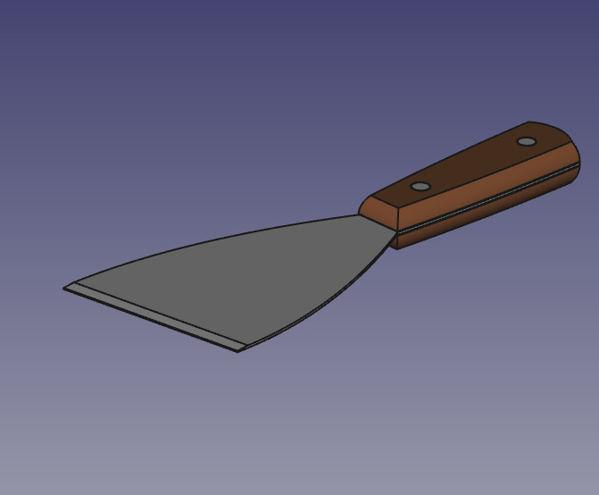
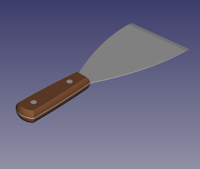
All of the key features of the scraper were reproduced in CAD, so I'm happy with the result here.
I think the "bodge pad" is an interesting solution to the problem of bevelling a non-axis-aligned blade, but I'm pretty confident it's not the best solution. It might be worth working out how to solve this using datum planes instead.
I was pleased to have learnt how to use SubtractivePipe. It's quite a powerful tool and I hope to use it more often in the future.
I think a better way of adding the mirrored scale would be to use one of the assembly workbenches (e.g. a2plus or Assembly4). I'd really like to learn to use one of these, particularly for their features allowing you to simulate relative movement and rotation of certain parts of a more complex object. Currently if I want to see how 2 parts fit together I just have to manually position them in space and check if everything looks right, and I don't have any decent way to see how the part would act if some of the pieces moved. Perhaps the next CAD Dojo project could be based around something like this.