
CAD Dojo
04: Nyloc nut
Mon 24 February 2020

Project
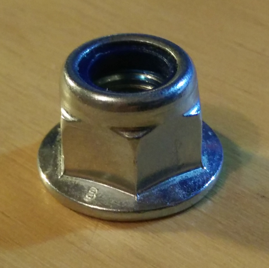
A nyloc nut is a nut that has a nylon insert pressed into it that prevents it from loosening. The nylon insert is not threaded which means it is always tight against the threads, which prevents the nut from working loose under vibration.
This project is to create a CAD model of an M12 flanged nyloc nut, 3D print it, and verify that it works. The real aim here is to get comfortable modelling threads in FreeCAD so that I no longer have to import threads as STL files produced in OpenSCAD.
Design
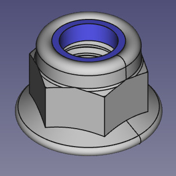
As always, I copied the key dimensions from the reference object using vernier calipers. Most of the design of the nut is straightforward. I started with a solid pad with a hexagonal cross-section, added a flange to the bottom using an additive revolve, and rounded the top with a subtractive revolve.
The tricky part is adding the threads. I initially tried to do this by making a helix in the "Part" workbench and sweeping a thread profile along it in "Part Design", cutting away from the inside of the nut, using SubtractivePipe. This worked for 1 helix section (which is 1 thread, or a single 360° rotation), but when I tried to add more sections I kept getting errors from FreeCAD about the resulting part not being solid. I don't know why. It worked fine when I was making an AdditivePipe on its own and not attaching it to any existing body:
But I couldn't get it to work for the actual nut.
My next attempt was to use the Fasteners workbench to create a length of M12 threaded rod, and then use the "Part" workbench "Cut" tool to subtract this from the body of the nut. This worked, but I'm not completely satisfied with it because the Fasteners workbench doesn't give much control over the threads it generates. You don't get to define a custom profile, diameter, or pitch, you just have to use metric threads with the default profile and pitch (for M12 this is 1.75mm). You also don't get to define clearances, which could be a problem when it comes to 3D printing: if you print your thread and it doesn't fit properly, there is not a lot you can do to the CAD model to fix it.

The Fasteners workbench describes the threaded rod it generates as "arbitrary length threaded rod for tapping holes", which implies that the dimensions are for a female thread rather than a male thread, although having looked closely at the generated threads, there is no clearance. The only difference between the "arbitrary length threaded rod for tapping holes" and the male threads that go into those holes is which side of the thread is filleted and which side is flat. The Fasteners workbench threads would be an inteference fit even if manufactured precisely to the CAD model specification!
Given that the thread wouldn't fit even if manufactured perfectly, and that 3D printers don't manufacture perfectly, I initially printed the nut with Slic3r's "XY size compensation" set to -0.3mm. This is quite a cool setting, it adds an absolute offset to the size of parts rather than scaling the entire thing up uniformly. You can see how the shape changes with the value, here changing between -1.0mm (smaller nut, bigger hole) and +1.0mm (bigger nut, smaller hole):
I've run out of Taulman 910 nylon for the time being, else that would have been an excellent choice. Instead I printed the nut in some grey PETG. Since the nut and the insert are to be made of the same material, I printed them together as one piece rather than trying to add the insert later.
The print with XY size compensation of -0.3mm still came out with threads that were too tight. I tightened it up anyway using a ratchet but it eventually split open at the end where the insert is, because the interference between the insert and the threads on the bolt is too tight for the plastic to withstand.
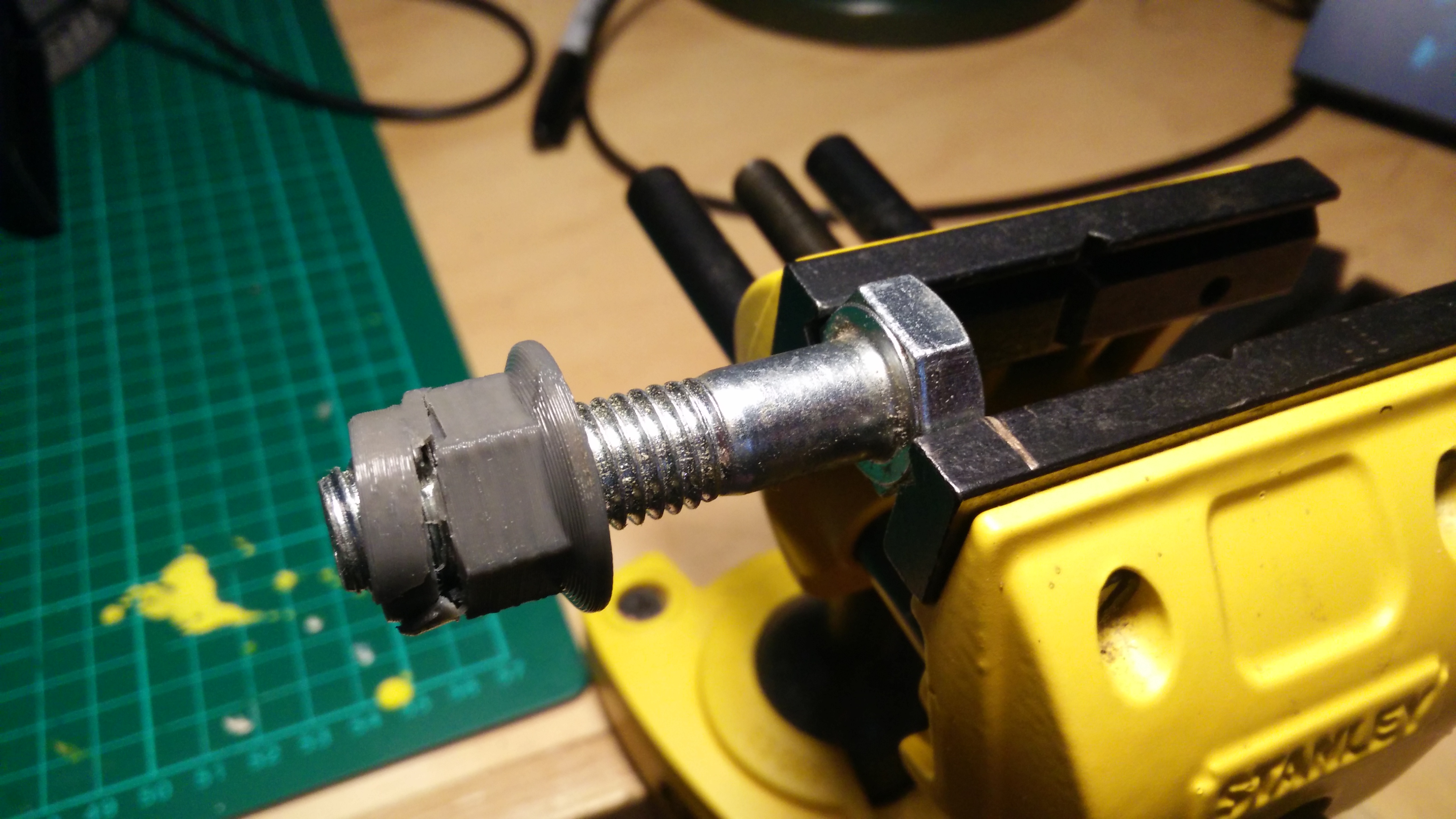
I increased the XY size compensation in steps of 0.1mm and found that it eventually printed usable threads at compensation of -0.6mm, although with this much offset, the hex part of the nut is no longer an acceptable fit in a 19mm socket and I had to use an 18mm socket instead.
You can see the nut in action in this YouTube video.
Evaluation
The model certainly looks like a nyloc nut, but the clearance issues with the thread means that making threads this way is basically unviable. There is no way to adjust the tolerances on the thread without also changing the dimensions of the rest of the model. This is a serious drawback in the Fasteners workbench and I might have a look at adding a clearance option to it.
I also don't know why using the Helix+SubtractivePipe method to make threads didn't work for me. I'll certainly have to revisit FreeCAD threading another time.